FAQ
General Program Features
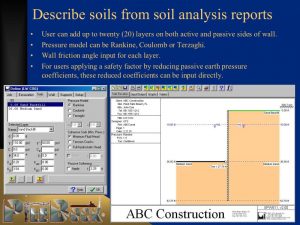
How do I add a new soil layer?
- Open the Soils page of the define box by double clicking the soil on the active side of a design.
- Click the New Layer button:
- Enter the depth of the top of the layer in the depth box.
- Select a soil from the database by clicking the down arrow to the right of the Name box. The soil parameters may be edited. Alternatively, enter a new soil name and properties in the relevant boxes without selecting from the database.
- Click the Apply button:
- The new layer is not added to the design until the Apply button is clicked.
How do I place a support above ground level?
- Open the Wall page of the define box by double clicking the sheet pile.
- Enter an Upstand in the box provided (eg. 1.0).
- Open the Supports page of the define box.
- Enter a negative value for the support position (eg. -0.5). The support must be within the upstand.
How do share load between two supports?
- Open the Supports page of the define box by double clicking an existing support.
- Place two frames close together (0.5m or nearer) using the Frames grid.
- Select the lower of the two supports in the grid.
- Click the Share load check box. The total linear load on the two frames is shared equally. A link is displayed in the main design diagram to indicate that load is being shared.
How many levels of wales may be entered? And what’s the difference between braces and walers?
Twenty (20). The options between braces and walers is really for presentation purposes; it informs the installer what kit is being installed. However, the waler does allow angled struts/anchors which the brace does not (but note that the displayed load is the linear load on the waler/brace, not a strut load).
Why does the pressure remain constant when a design is edited?
Changes in soil parameters, water tables, etc sometimes produce no change in the calculated net pressure. This is probably due to the presence of soils with a high cohesion. In such cases, the calculated soil pressure may be negative, and the pressure values are being calculated using the minimum equivalent fluid pressure, MEFP.
How do I change units?
You can change units in the Setup page of the define box. The best time to do this is when you first open a job. Doing so later can create problems with the database; the only way to deal with it then is to reinstall the program. If you work consistently in U.S. units, the best way to switch over is to do as follows when you first use the program:
- Open a new job.
- Double click on the center of the screen, in the drawing.
- Click the “Setup” tab in the define box that appears.
- Click on the “Imperial/U.S.” button.
You can then proceed to enter the rest of the job information. If you do have to reinstall the program and have made entries to the database, you can do the following:
- Select the unit setting which gives metric VALUES (eg. E should be 2.1E8).
- Exit the software.
- Copy the files Client.db, Sheet.db and Soil.db from the Pile BuckData folder to another location. These will hold metric values.
- Uninstall SPW911 and ensure the folder Program FilesPile Buck is deleted.
- Reinstall SPW911. It should be already set to metric units.
- Copy the files Client.db, Sheet.db and Soil.db, which you copied above, back to the Pile BuckData folder.
How do I model soldier piles using SPW 911?
We have a PDF article on this subject; Please email Pile Buck to request a download.
What kind of surcharges can be input into the program?
Only uniform surcharges can be input into the program. The program does not consider point loads, strip loads, etc.
When driving a cofferdam to rock (for keying bridge bent footings into rock), how do I show this in the define soil layers screen?
Define a new soil with appropriate properties for rock, e.g., high cohesion, etc.
Does SPW 911 handle broken back fills? Horizontal loads to be applied to the sheeting to model guardrail impacts?
No.
I have a situation where the soil at the base of the sheeting is sloping down and away from the base at a 3:1 (3 horizontal, 1 vertical) slope. How can this be modeled in SPW 911?
It depends very much on the ground.
- In cohesionless soils, you could draw a line from the bottom of the wall at an angle of phi (angle of internal soil friction) to the horizontal. Draw a horizontal line from where this meets the slope on the passive side back to the wall. The distance from this point to the original point (where the soil meets the wall) is the height “X” which you can ignore.
- With cohesive soils, the problem is not so acute, where the shear strength is much higher. Some provisions would probably need to be made in the case of soft clays, but it would be up the judgment of the engineer.
Can SPW 911 be used to design wood or concrete sheeting walls?
Yes, if they enter appropriate properties (E & I values especially).
I entered data for a new sheet pile section into the database while analysing a wall design. While analysing the wall, I realized I needed to change some of the sheet pile properties. But there’s no change in the results from the program. What’s going on?
You need to either a) save the results, exit the analysis and restart it or b) change the sheeting momentarily to another section, then change it back to the one you’re working on.
Can I work to elevation vs. depth?
No, the datum is fixed at ground level. To change this would interfere with the calculation methods of the program.
Why would the anchor force for a single propped or anchored bulkhead be greater than the maximum shear?
Any concentrated force on a beam — and this is what you’re basically dealing with with a sheet pile — creates a discontinuity in the shear diagram equal to the magnitude of the concentrated load. Thus, the difference between the two shear values immediately on either side of the support will equal the magnitude of the support load.
We are noticing that the same input is giving us different results. For example: We input data (soil types and properties, surcharges, depth of excavation, etc….) and the program gives us results (toe, bending, wale forces, etc…….). We then change our data to see what different results we get. That is fine but when we change back to the original data we will get different results than what was input before. What’s going on?
The soil K values have probably been modified inadvertently. Check the K values before and after the changes – they must be the same if the same results are to be found. For example, load Demo2 and note P, waler load, toe, etc. Print the Input/Output page. Open the Excavation page, and select a 20 degree slope – P, etc all change. Now select level ground again – they change again, but do not go back to what they were. Print the Input/Output page and compare the soil K values with the previous page – they are different. This happens because the K values are recalculated to their theoretical values, based on phi, when slope or level ground is selected. However, the K values in the Demo2 file do not agree with the theoretical values, calculated from phi (they don’t agree because they were set differently in the original source of this example – see below). Similar things can happen when the pressure model is changed. To summarize: if toe, frame load, bending moment, etc change, then it’s a result of a different pressure graph. If the pressure appears to have changed, then check the K values at each depth. Email us if this does not solve the problem.
The steel piling have a limiting stress of 25 ksi for maximum bending moment. The sheeting I am considering will allow more. How can I change it?
The 25 ksi value was placed for conservatism. You can change this value in the database for each individual section.
Can the active and passive soil properties be entered as separate layers?
No; all layers in SPW 911 are horizontal.
I am designing a wall with a sloping backfill. I have changed the water level. If I change the pressure method to, say, Coulomb and then back to Rankine, the pile length reduces signficantly. What’s going on?
The soil coefficients are changed when you switch from Rankine to Coulomb and back again. Each time you switch, the K values revert to their theoretical values under the selected model. The pile length used when you switch back to Rankine is because a different pressure is being calculated due to the changed soil coefficients.
How can I add different sections to the sheetpile database and not lose the information?
You need to “post” a change after making a new entry, by selecting another record or clicking the “tick” button on the navigation bar – see the Help file, under “Databases – Database editing” for more details.
Program Operation
How do I ensure graphics and tables are set correctly?
Your computer should be set to Small Fonts when using SPW911, or some tabular output will extend beyond the right edge of the window or overlap. To reset your computer to small fonts:
- Click Start > Settings > Control Panel > Display
- Select Small Fonts on the Settings page of the dialog box.
- You may also prefer to set the following on the same page, although the settings shown are not critical:
- Colour Palette should be set at High Colour (16 bit). This produces shading on the side elevation diagram. Other settings give a hatched pattern.
- Desktop Area should be set at 800 x 600 pixels. The side elevation diagram fits the screen exactly on this setting when Fit Screen is set. Less than 800 x 600 will mean that you cannot see the whole diagram, even with Fit Screen set, while larger than 800 x 600 will result in white space around the diagram (this white space can be useful in some cases). Note, however, that some software (e.g. AUTOCAD) may require a larger setting, in which case see below.
- Set the Show settings icon on task bar check box. This provides quick access to the Color Palette/Desktop Area settings.
- The computer must be rebooted after changing the Font Size, but the Colour Palette/Desktop Area may be changed at any time, even while the software is running.
How to I Customise SPW 911?
Your company logo or other information may be displayed in the area at the left side of the title bar below the main design area. To use this area, create a bitmap file called MyLogo, and save it in the Data folder of the install directory directory. The bitmap will be plotted in the appropriate area. The bitmap may be any size as it is scaled to fit the space available. However, as the maximum display area provided is 266 pixels x 70 pixels, the bitmap used should not be much larger than this. Your company address and other contact details can be displayed in the title bar below a design. They can be altered in the Setup page of the define box. Double click anywhere on a design and select the Setup tab for this page. Alternatively, double click the relevant hotspot to open the define box at the Setup page.
When I print output, part of the title block has info being printed outside of it, and the input data sheet runs outside the printable area and I cannot see any output. What is going on?
If this is happening on the screen, then see the Help file, under “Frequently asked questions – How do I ensure graphics/tables are displayed correctly?” If the problem is when printing, then you may have the wrong driver selected – check the driver agrees exactly with the printer in use. Please email Pile Buck with details of the printer, etc if the problem persists.
What if I receive a Borland Error Message?
The first thing you need to find out is, “What other Borland products do you have installed? If there are no other Borland products, or one(s) that he will not be using simultaneously with SPW911, it should be OK to proceed with the install. If this is not the case, and there are other Borland products, locate the following files on your hard drive: USA.BLL, EUROPE.BLL, CEUROPE.BLL, CHARSET.BLL, OTHER.BLL, IDAPI32.CNF. You should have “Hidden Files” switched ON to locate them, and they should all be in the same folder “Program FilesBorlandCommon FilesBDE.” If they are not in this folder, reinstall your other Borland product(s), using the suggested default folders. It should be noted that none of this may be necessary. It is entirely possible that SPW 911 will work properly if the program installation is completed.
My colors in Windows 2000 are wrong. Or my computer is giving a new error message. Why?
Our graphs have been printing improperly. Our scales on our graphs have been printing black blocks instead of the numbers. For some reason the Pressure Graph prints properly but not the others.
These problems (mainly in Windows 2000 and Me; probably in XP also) are due to changes in Windows that Microsoft has made. These compromise the “backward compatibility” of the newer operating systems with software developed for and compatible with older systems. We have a fix for these problems and if you would like it click here and email us with your request. In some cases, color printers will still have problems, in which case turn the color graphics off in the Setup page.
Why is there no written documentation with SPW 911? And why do the methods used by the program not exactly correspond with the Pile Buck Steel Sheet Pile Design Manual?
“Online” style documentation is normative for computer programs today. It is especially helpful when revisions take place; the documentation can be changed and updated much more readily. As far as the methodology is concerned, the methods used in SPW 911 are described in the British Steel Piling Handbook (7th Edition), which can be viewed at corusconstruction.com. As is very common with foundation design, there are many variations on design methods for the various types of structures and this is certainly true with sheet piling. It is not practical to include all of them in one computer program. We should also note that the Pile Buck Steel Sheet Pile Design Manual has been superceded by Sheet Pile Design by Pile Buck, which not only harmonizes the methodology but also gives worked examples using SPW 911.
I opened a new program. Got up to the “Your Company Name” Side Elevation tab. The bottom of the screen states “Double click to open Define dialog”. I tried to click all over the screen but nothing happens. I tried uninstalling and reinstalling several times. What can I do to get to the define dialog?
- Open a new design by clicking the “New” icon at the top left of the toolbar.
- Double click (left button) anywhere in the white area of the main design window. You may be double clicking too slowly – try to do it quicker.
- A second window should open to let you edit designs.
- Assuming this doesn’t work, confirm that you can open the demonstration files in the Designs folder.
- Check your mouse is OK and registering double clicks.
I am having difficulty getting a moment in my sheet pile wall. I did start off with metric,but then reinstalled program and used English units. When I click on show moment graph icon, I get the following statement : “Access violation at address 004ccb59 Read of address 00972974”.
This type of error may happen in Windows XP if you do not have “admin” (administrator) privileges and full access to the directory c:Program FilesPile Buck. If you can obtain these, this type of error message may be eliminated.
Factors of Safety
How do I check my factors of safety?
The “Reporting on Design” function lists any potential design problems identified by the software. Items considered are bending moment (compared with allowed sheet moment), toe smaller than recommended, danger of rotation in “no toe” designs and water levels. A check is also made on soil densities, and a warning is displayed if a submerged density seems large compared with the bulk density. Other checks will be added as they are identified. Note that Rules of thumb can be switched on/off in the Wall page of the define box. These can improve design safety.
I started working with SPW 911 and found that the passive earth pressure coefficient was not reduced by the reduction factor (R) as it is required by AASHTO Tables 5.5.2.C and 5.5.2.D. Why not?
With cantilever walls, safety factors can be dealt with in several ways. One of these is to divide the passive earth pressure coefficients by a reduction factors (typically 1.5 to 2.0.) The other way is to compute the equilibrium condition for summation of forces and then add toe length. SPW 911 uses the latter approach. If you want to reduce the passive earth pressure coefficient, you can do so directly in the soils page.
Can the factor of safety (FOS) be set or changed? How is this done?
User can select Free Earth Support (FOS = 2) or Fixed Earth Support (FOS not applicable). User can enter a toe (including 0) manually. In all cases, FOS can be calculated and displayed. To change the factor of safety:
I am designing a cantilever wall, and would like a factor of safety of 1.4. Program determines the penetration based soil layers and rule of thumb. I’ve tried adjusting Kpc value of embedments layer. This increases the penetration but does not increase the factor of safety, and has a bad effect on the deflection at the pile top. What’s the best way to deal with this?
Open the “Wall” page, switch “Automatic” off, and enter the toe manually.
Is the factor of safety based upon net pressures, i.e. active minus passive pressures or can it be set separately for active and passive pressures?
Water Modeling
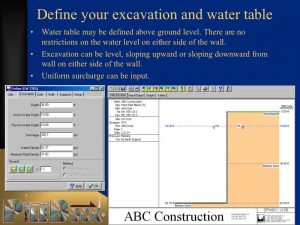
How do I define water above ground level?
- Open the Excavation page of the define box by double clicking the margin beside the main diagram.
- Enter a negative value for the active or passive water depth.
How is water modelled in cohesive soils?
Pressure is calculated as outlined in the British Steel Piling Handbook (7th Edition), Ch. 4 (BSPH) and the Pile Buck Steel Sheet Piling Design Manual. Different active and passive pressure coefficients are used for the Rankine and Coulomb models. The net pressure is calculated by finding the sum of the active and passive earth and water pressures:
Active and passive earth pressures are given by:
- pa = g k Ka – Kac C
- pp = g h Kp + Kpc C
It is recommended that a minimum standard surcharge of 10kN/m&Mac178; be applied to the surface of the retained soil in the design of all retaining walls (Ref: BS 8002: 1994). This is the default in SPW911, but the value may be changed in the Excavation page of the define box. Additional loading due to vehicle movement, foundations, etc can be modelled by increasing the standard surcharge.
Water pressure at any depth, d, is given by: pw = (d – dw) gw In the earth and water pressure equations: Granular soils (C = 0;f > 0): bulk and submerged densities are used above and below the water table respectively. Water pressure is then calculated within each soil layer. Cohesive soils (C >0;f = 0): bulk density is used above and below the water table. The limit of water pressure in cohesive strata is assumed to be the depth at which the water pressure equals the earth pressure. Mixed soils (C > 0;f > 0): bulk and submerged densities are used above and below the water table respectively. Water pressure is applied within each mixed soil layer.
- Minimum equivalent fluid pressure (MEFP)
The calculated net pressure can have a negative value when soils with high cohesions exist in an excavation, and the pressure is then assumed to be zero. In such cases, allowance should be made for the intrusion of water between the soil and the sheet piles by applying full hydrostatic pressure. Full hydrostatic pressure may be selected in the Soils page of the define box. Where ground water is unlikely to be present, an alternative substitution for zero net pressure in cohesive soils is to assume a pressure due to an equivalent fluid of density 5kN/m3 (Re The MEFP is applied after all other pressure sources have been applied. The MEFP can be ignored by setting the minimum fluid density to 0kN/m2.fon
Water may penetrate to considerable depths in cohesive soils via tension cracks. These may open in the immediate short term to a depth given by: (2C – Q)/g Tension cracks in cohesive soils may be defined to a specified depth in the Soils page of the define box. When applied, the net active pressure is the maximum of calculated soil pressure and water pressure within the tension crack , and the maximum of calculated soil pressure and MEFP below the tension crack.
Passive softening can occur when soft cohesive soils exist at dredge or excavation levels (Ref: BSPH, pg. 5/8). Passive softening can be switched on/off in the Soils page of the define box. If passive softening is applied, then the cohesion of the passive side is assumed to increase linearly from zero to the full value over the passive softening depth entered. The default value of the passive softening depth is 1m, but this may be varied. Note: In some cases, the net pressure above excavation level can be negative (eg. when the passive water level is less than the excavation depth). In such instances, the net pressure is assumed to be zero.
On Page 34 of the Pile Buck Steel Sheet Piling Design Manual, Fig. 12b shows the net water pressure on sheet piling with varying water levels as set forth by Terzaghi. Does SPW 911 treat water pressure in this same way?
SPW911 does not exactly follow the method shown on pg. 34, but it can give effectively the same result if appropriate settings are chosen. If anything, the software probably predicts greater pressure which will result in safer designs. More detailed information on this subject can be found in Sheet Pile Design by Pile Buck.
Should minimum fluid density be set to 0 if full hydrostatic pressure is used?
Set to 0 to ignore min. fluid pressure, set to 9.81kN/m2 (62.4 psf) to apply full hydrostatic in cohesive soils.
Terzaghi Pressure Distributions and Braced Cofferdams
I would like to know if this program is appropriate for designing braced cofferdams? Will it accomodate a water level differential and will it allow the use of empirical pressure diagrams?
SPW 911 is suitable for designing braced cofferdams, as it allows the use of Terzaghi and Peck wall pressure profiles. It does allow a water differential but does not allow the use of empirical pressure diagrams.In designing braced cofferdams, however, keep in mind that SPW 911 does not compute base stability; this must be checked separately. Also, SPW 911 assumes that the wall pressure at the excavation level are continued below the excavation line. In the case of stiff clays, this means zero on the soil side of the excavation. If this is not desirable, an alternate method of computation can be found in NAVFAC DM 7.02. More information on Terzaghi pressure profiles and their application can be found in the Sheet Pile Design by Pile Buck.
Using Terzaghi design pressures, what do the factors m & a represent and can they be modified?
m – depends on soil properties; a – 0.2 or 0.4 for temp/permanent works; both can be changed Ref: Pile Buck Steel Sheet Piling Design Manual, pg 119 (uses ‘n’ instead of ‘a’)
I was designing a cantilever wall with Terzaghi earth pressure assumptions. My output looks strange compared to manual calculations. What’s going on?
The Terzaghi pressure model is not really appropriate to cantilevers – it’s best used to calculate strut loads in anchored excavations. When Terzaghi is selected, Rankine is used for the pressure below the excavation depth as no other method is documented. Terzaghi is not recommended for bending moment calculations.
In a design with multiple walers, how is the required toe calculated in granular soils?
When more than one support is present, the toe and load on the lowest frame are found by considering the lowest span as a singly supported wall. Loads on the frames above the lowest are found using the current load model. The load model can be by a) Area Distribution (as described in the Sheet Pile Design by Pile Buck) or b) the Hinge Method. The method used is selected in the Supports page of the box.