


Pier & Wharf Construction Part II: Structural Design

View the complete version here.
As with any construction project, the structural design of piers and wharves is one of the most important elements of the undertaking. However, there are unique elements at work with this type of construction that require special consideration. This includes lateral and horizontal forces on the marine structure, corrosion from water, and the possibility of seismic activity. Understanding these issues will allow you to incorporate these factors into your design plan and come up with an appropriate final design.
Types of Construction
Open piers and wharves can be constructed in one of three ways. The conventional method involves a system of piles (either plumb or batter) on which a deck can be constructed. These piles can be made of a number of different types of materials, including steel, precast concrete, precast prestressed concrete, timber, or a steel/concrete composite. The deck is typically made a concrete, although timber may be used for light-duty facilities.
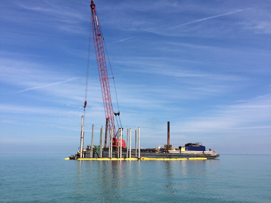
Alternatively, a jack-up barge can be used to build an open pier or wharf. Using this method, a structural steel seaworthy barge is floated into position, loaded with steel caissons, a crane, and other necessary tools and materials. The barge is then towed to the site. Then steel caissons are lowered to the harbor bottom by the crane. The caissons are seated into the harbor bottom by dead weight; once the barge deck is jacked to the required elevation and locked, each caisson is released from its jack and driven to the required penetration or refusal. The hull of the barge is then welded to the barge, the jacks are removed, and the caissons are cut flush with the deck and capped. The caissons may also be filled with sand to avoid buoyancy issues.
The barge is often outfitted with all necessary equipment, such as deck fittings, ship fenders, and utilities. It can then be jacked into position. The barge can be elevated in steps using circular pneumatic gripping jacks. Once utility tie-ins are completed, the barge will be ready to receive ships.
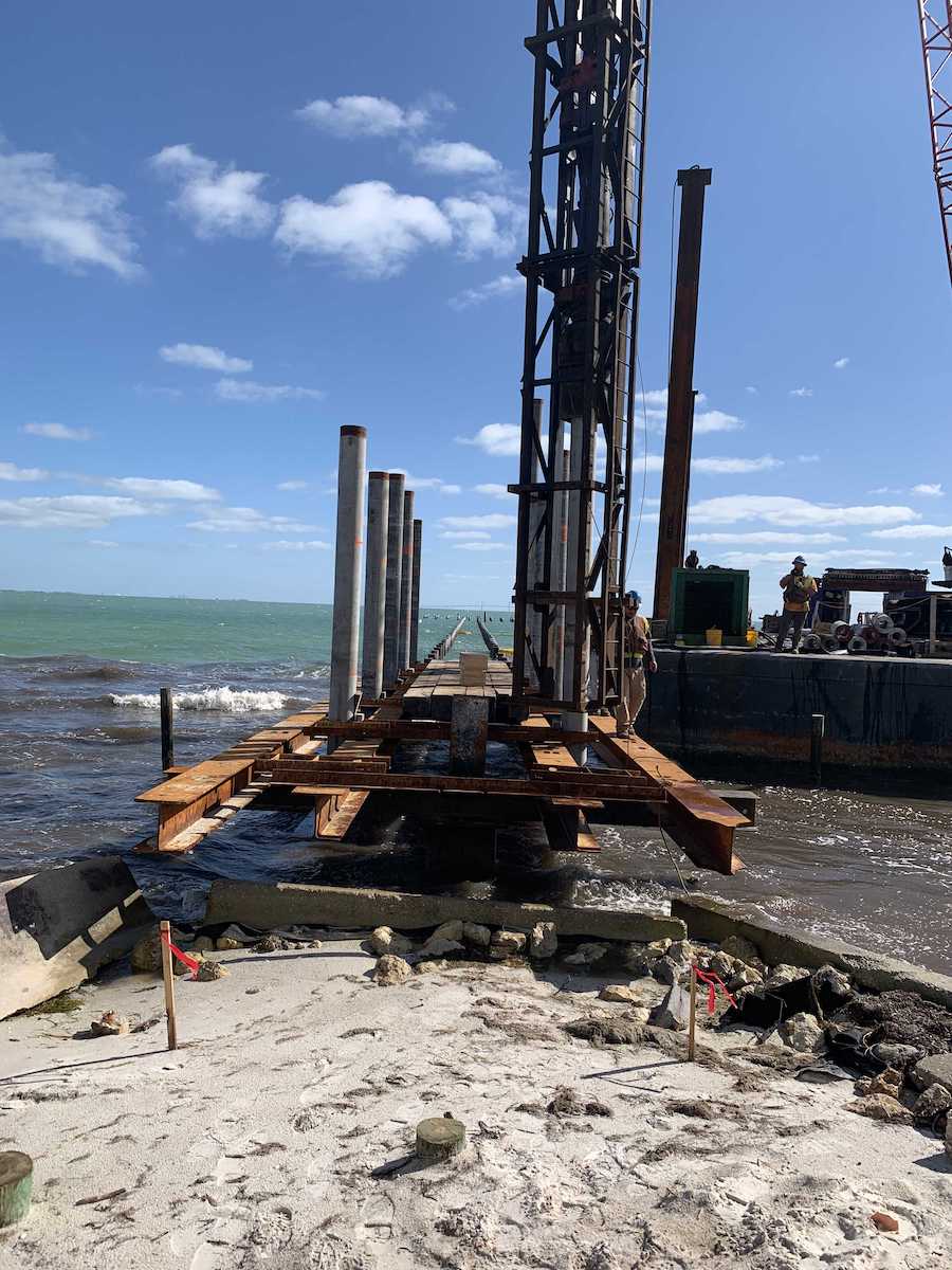
Finally, a template construction can be used to construct an open pier or wharf. This involves fabricating the structural components of the pier and then transporting these units to the site via barge. Once at the site, the prefabricated units are erected to form the facility. A template pier may be outfitted with all necessary utilities, deck fittings and other services that may be necessary to allow it to receive ships as soon as utility tie-ins are completed.
With template-type piers and wharves, the prefabricated units are made of structural steel and include templates, deck assemblies such as cap beams on trusses and stringers, fender units, decking (either timber or concrete), tubular piles, fittings and other hardware. The template consists of four or more tubular columns that are connected with bracing and welded together to form a structure that is approximately equal to the depth of the water in which it will be installed. Contractors use a floating crane to transfer the template from the barge and place it on the harbor bottom, where steel piles are then driven through the columns. After this, the space between the piles and columns is filed with grout. Finally, the remaining components are positioned to complete the facility.
Construction Materials
There are six primary types of materials that may be used in building piers and wharves. The material chosen will depend on a number of factors, including the application and the conditions of the project site.
Timber is often used in the construction of light-duty piers and wharves, such as for fueling, temporary, and degaussing/deperming facilities. It should not be used for major functional piers and wharves, such as berthing, repairs, fitting out/refit, and supply facilities that are subject to highly-concentrated wheel loads. Timber is best reserved for use in fender systems, dolphins, walkways, utility trays, and deck-supported small buildings.
If timber is used, it should be pressure treated with oilborne or waterborne chemical preservative to protect against the effects of decay, insects and marine borings. In less severe environments, fender pilings can be left untreated. However, in warmer waters, both treatments should be applied, as severe marine borer activity is anticipated. Treatment should be made after all holes and cuts are made. Applying treatment in the field can be difficult, particularly below mean low water. When possible, piers and wharves should be designed so that cuts, holes, bracings and connections in timber should be avoided below mean low water. In addition, all connection hardware should be appropriate for saltwater immersion and exposure. All timber above the water should be treated with waterborne preservatives, as it will not stain clothes or smear on equipment.
Steel can be used in all types of marine structures when it is protected against corrosion, typically by coal tar expose or other marine coating and cathodic protection systems. Steel can be used in template and jack-up barge construction at advance base facilities, as piles in areas of high seismic activity or where high lateral forces must be resisted, as fender piles and fender panels, and where difficult driving is anticipated. However, because steel is costly and requires maintenance, if other construction material is available, that other material may be a better choice.
Concrete is often the top option for pier and wharf construction given its durability in the marine environment. Unlike other materials, concrete is not susceptible to marine borers or insects, and is fireproof. It is also an economical choice for floating structures, and can be used when nonmagnetic properties are desired in degaussing/deperming facilities. Proper design and construction of concrete in pier and wharf construction is necessary. This includes prestressing precast concrete piles to resist the tensile forces encountered during driving, and ensuring proper mix design.
Composite piles of concrete and steel can also be used to construct piers and wharves. This typically takes the form of either steel H-piles with a concrete casing or concrete-filled pipe piles.
Aluminum can be used for deck-supported structures and to support piping and conduits, but unprotected aluminum cannot be used under water or in the splash zone due to the likelihood of corrosion. Aluminum also must be electrically isolated through the use of nonconductive gaskets, washers, or bolt sleeves. Aluminum is most commonly used in the structure of degaussing/deperming facilities.
Finally, plastics are becoming a more common material option in waterfront construction. In particular, fiberglass-reinforced plastics and ultra high molecular weight plastics are durable in the marine environment. Some types are also highly resistant to abrasion. Because the uses of these plastics are relatively new in pier and wharf construction, caution should be exercised when selecting them for a project.
Deck Structure Design
There are a number of factors that must be considered when designing the structure of a deck for a pier and wharf. Generally, concrete is the best material for deck framing, as steel, steel/concrete composite, timber and timer/concrete composite are more costly and require more maintenance than concrete. In addition, concrete is more durable and has a longer lifecycle than other materials.
The concrete deck framing should consist of cast-in-place, precast or composite concrete slabs which are supported on pile caps. If loads will be concentrated on the deck, the slab should be solid with high punching shear resistance. Thin slabs should not be used, as they may spall along corners and edges. If high concentrated loads are not specified, voided slabs may be used. To properly distribute horizontal loads, the pier and wharf decks should be continuous, with a minimal number of expansion joints. When placing expansion joints, the deck on either side should be supported by a pile cap or girder.
The deck should be designed so that vertical concentrated wheel loads can be placed anywhere on it, as operational control is not possible. In addition, trench covers, access hatch covers and utilizer covers should also be able to handle concentrated loads so that they are accessible to mobile equipment. Some spaces on the deck may be excluded from the concentrated load requirement, or designed for lesser loads, provided that a physical barrier (such as a curb or railing) isolates that area from vehicle access.
Careful consideration must be given to the distribution of concentrated loads. For truck, forklift and straddle carriers, concentrated wheel loads should be applied through relatively small footprints to the structure of the deck itself. The distribution of these loads and computation of maximum moments and shears can be calculated using Adolf Pucher’s Influence Surfaces for Elastic Plates. For mobile crane float loading, the influence surface approach is recommended. If rail-mounted crane loading will be utilized on a pier or wharf, the wheel loads can be converted to an equivalent line load if the crane support beams are at least 2 feet deep and the wheel spacing of the cranes is no more than 4 feet. Finally, for ballasted deck constructions, if a 45 degree distribution through the ballast and paving, then the footprint of concentrated loads can be increased.
The deck of a pier and wharf will also be required to receive lateral loads from the berthing and mooring of ships. The structure must be able to distribute these loads to pile bents or to the bulkhead, which will vary based on the relative stiffness of the pile bents and other factors. This should be calculated by hand or through a stiffness analysis using a software program prior to designing a deck structure.
Berthing forces occur when a ship berths along a deck and transmits the force along the contact length of the fender system. This force is then distributed by the diaphragm action of the deck to the pile bents. Depending on the type of wharf, the berthing forces may be transmitted to retained upland fill, directly to the fill, or resisted by the piles. If fender piles are used together with separators, only the part of the load transmitted at the deck level must be considered as part of the deck structure design.
In addition to berthing forces, mooring forces must be taken into account when designing a deck structure. These forces act away from piers or wharves, and are transmitted to the deck through the fittings where mooring lines are attached.
Pile caps (and therefore pile bents) are often oriented transverse to the length of the structure for convenience and cost-effectiveness during construction. Generally, longitudinal pile caps are not needed when pile caps are oriented in this way unless necessary for seismic resistance or crane track supports. Deck structure design should factor in moments and shears on pile caps, as well as the elastic shortening of the piles and the impact of soil deformation. A stiffness analysis is the best way to achieve the proper design of this element.
Substructure Design
Beyond the deck, contractors must also carefully plan what supports the pier and wharf. Substructure design is vital to the overall integrity of any marine facility project.
Pile bent framing is the most common type of system for open piers and wharves. There are many types of pile bent framing systems available, with the best option depending on the type of project, level of seismic activities, budget, and other factors.
An all plumb pile system involves setting up the piles and caps in such a way that they form a moment frame to resist the lateral load through flexural stiffness. This system works best for axial loads, and less for bending moments. The drawback of this system is that lateral deflection will be high even for small lateral loads, and that side sway is not prevented. In addition, if piles have different unsupported heights, the shorter piles will take on the bulk of the lateral load. This makes an all plumb pile system most effective for shallow waters and light lateral loads.
Plumb/batter pile systems have plumb piles that handle vertical loads and batter piles that resist lateral loads, combining to make a “truss action.” Through the system, very high forces are transmitted to the caps, requiring careful design to resist the forces. This type of system is very cost-effective because the lateral loads are mostly resisted by the stiffness of the batter piles. This also makes plumb/batter pile systems a good choice for areas of high seismic activity.
An all batter pile system is a compromise between an all plumb system and a plumb/batter pile system. The batter slope may be close to vertical with some systems. It can be a cost-effective system, and is useful for areas with high levels of seismic activity.
Piles are also subjected to lateral loads that act along the length of the pile. This includes action from currents and waves, which act against piles at or near the water level. Sloping fill loads come from the lateral movement of the soil around the piles under the structure; this movement is then transmitted along the shaft of the piles. Dynamic fill loads exert pressure on piles that are subjected to seismic forces, as vertical and batter piles move with the surrounding soil during an earthquake. If the soil liquifies or if slope failure occurs, the piles may move excessively, causing damaging to both the piles and the structure. In this case, unstable materials should be removed and then replaced.
Piles are typically made out of either steel, concrete, or a composite of the two. Timber piles are sometimes used for structures that bear light loads, or for fender systems. The most important considerations in choosing a pile material is the load capacity, geotechnical factors, and life-cycle costs. Steel piles should be coated with a protective system or filled with sand to increase durability and reduce maintenance. Similarly, concrete piles should be prestressed to reduce cracking during driving. Piles should also be proportioned properly to resist high compressive and tensile stresses during driving. To control driving stress with concrete piles, contractors should specify frequent cushion replacement and the use of hammers that can adjust driving energy.
Solid cellular structure are gravity-retaining structures that form from the interconnection of straight steel sheet piles and cells. Clean granular fill should be used to fill the cells to increase shear resistance. Circular cell structures have individual large diameter circles that are connected by smaller diameter arcs. Each cell must be filled before the next cell can be started, and each cell is a self-supporting unit. A diaphragm cell structure involves two sets of circular arcs that are connected together by diaphragms running perpendicular to the axis of the structure. The cells have to be filled in stages so that the fill is equal in height. This type of structure is generally preferable for marine structures. A third type, a cloverleaf cell structure, is a modification of the circular cell structure. It is used in deep water where the diaphragm type is not appropriate.
For solid structures, granular free-draining material should be provided next to bulkheads. This fill should go from the dredged bottom to the underside of the pavement on grade, and then graded to act as a filter.
Finally, when designing a substructure, contractors should take into account the possibility of deterioration. Doing so allows contractors to take the necessary steps to ameliorate these issues. First, marine borers are a common problem with substructures. However, the only material that will be affected by marine borers is wood piles. A preventative treatment can be applied to reduce the impact of marine borers; this treatment should be selected based on the type of organisms present in the local water. Second, corrosion is an issue for steel and some concrete piles, particularly as they get wet and they dry again. Steel piles will require a good paint or cathodic protection to prevent corrosion. Alternatively, a concrete jacket may be used in the splash zone. Prestressed concrete piles in properly mixed ratios may help to reduce corrosion. Third, abrasion from floating debris and ice in open piers and wharves may cause damage to concrete piles. Timber jackets may help to reduce the impact of abrasion.
Floating Structures
Some pier and wharf projects require the design and construction of a floating structure. This requires special design considerations.
Floating concrete structures can be used where fixed piers or wharves are either impractical or too costly. Concrete is a good material choice for this type of design, as it is dense and impermeable when properly mixed and prestressed. It requires little to no maintenance, and offers mass, which provides a more stable structure by increasing the roll period.
Floating structures have to be operating similarly to ships, in that contractors must avoid over stressing or sinking the structure. As a result, load application and ballast management are of utmost importance. At least 45% of the structure will be submerged, so this will give a general idea of the minimum depth of the structure (freeboard requirement). The structure must be compartmentalized to provide buoyancy chambers that are watertight, as well as support to the top and bottom decks. This is often accomplished through either interlocking chambers (a honeycomb) or through a rectangular grid of bulkheads. As the number of internal framing elements increase, the cost will rise as well. The storage of liquids should be avoided in compartments because it may damage the concrete.
Aboard a floating structure, pile and mooring lines can be used to moor vessels. The appropriate anchorage system will depend primarily on the foundation soils. A pile system can consist of plumb or battered steel pipe piles. This type of anchorage is best for shallow waters where the use of anchors is difficult. Piles may not be an option if the soil is of poor quality. In addition, piles may reduce buoyancy and usable deck surface area, and make it more difficult to move the structure elsewhere. A mooring line system should involve the use of taut lines (held by anchors) to hold the structure in position. This type of system requires monitoring of the lines and the potential need to prepare the bottom in the event of poor soil conditions.
Designing a floating pier and wharf involves two aspects: local and global design. As an initial matter, the structural framing includes prestressed flat plate elements that are connected to form a compartmented box. Local design of all of the plating elements is controlled by hydrostatic loads; the hydrostatic head should equal the full depth of the structure. The global design should ensure that the loads that are applied to the flat plate elements are transmitted to the whole structure. Prestressing should be done for both serviceability and strength, as well as to improve watertightness at joints. In addition, the concrete mix should be carefully controlled to ensure watertightness and durability.
On floating structures, fender stations must take reaction input in order to perform properly. There are three types of fenders that are recommended for floating piers and wharves: foam-filmed, buckling cell and delta. Each type should be provided with sufficient overcapacity, so that the fenders have the ability to resist extreme berthing energy. Foam-filled fenders have the ability to absorb large amounts of energy with small reaction input to the structure. They can also be moved along the face of the structure. Buckling cell fenders also provide large energy absorption with small reaction input, and can be mounted directly on external plating. Finally, delta fenders offer large energy absorption capacity, but provide a larger reaction input to the structure. Delta fenders can be mounted onto external plating, but require additional stiffening or buttresses to transfer reaction to the structure.
Mooring Hardware
On piers and wharves, ships are generally moored to bitts, cleats and bollards. They may also be tied to a quick-release hook. A ship’s position on a berth is usually dictated by utility hookups and brow location requirements, with the crew using whatever mooring hardware is convenient. This may result in lines being tied to lower capacity cleats while higher capacity cleats are available. For this reason, contractors may choose to use just one type of high capacity mooring hardware throughout the facility.
There are 6 types of hardware that are typically used for mooring. Bollards are cast steel fittings consisting of a single column that extends up from a baseplate. A bollard is secured to a strong point of a structure, and is used in checking the motion of a ship or for securing a ship that has been placed in its final moored position. If the bollards lack ears, they should not be used in facilities where there will be a high vertical angle of the mooring line.
Bitts are short, double-column cast-steel fittings that are fastened to the deck of berthing facilities. They are helpful for quickly tying and releasing mooring lines, and for guiding lines to other hardware. They are often used to snub and secure vessels.
Cleats are cast steel deck fittings that have two arms that are used to secure the mooring lines of small crafts. They are often used by line handling crews because the possibility of slipping is low, but they can be overloaded given their relatively low capacity.
Chocks are cast steel deck fittings that can be either stationary or roller-equipped. They are used to train the direction of a mooring line, and may be open at the top, permanently closed, or closed by a hinged closing piece.
Capstans are small electric winches (of 5 to 10 horsepower) with a drum that rotates around a vertical axis. It is used for ships with winch-mounted wire rope mooring lines that require greater pulling power than that offered by deck hands. Capstans are also used as guidance to berth ships in dry-docks and slip-type berths.
Quick-release hooks is a deck fitting used to receive mooring lines. This type of mounting hardware is usually mounted on a swivel base. A tug on the release mechanism or the use of a tag line from the ship unfastens the mooring line if a ship needs to leave quickly.
Mooring hardware often receives more than one line at a time. The strength of mooring hardware should be determined by the breaking strength of the strongest mooring line that may be fastened to it. Generally, the minimum strength of mooring hardware should be one and one half to two times the breaking strength of the strongest mooring line anticipated (which may be anywhere from 50 tons to 200 tons).
Mooring hardware should be placed in such a way to allow ships of different sizes and classes to berth at the facility. As a general rule, hardware spaced at 60 feet on centers along the berthing face will likely provide the number of fittings required to secure the ships.
Mooring Dolphins
A mooring dolphin is a small, independent structure that can be constructed at one or both ends of a wharf to allow for a more favorable angle for mooring lines. This dolphin can be accessed through a walkway, and then the mooring line can be attached to hardware on the dolphin.
The load for the mooring dolphin comes from the tension in the mooring line. It is usually constructed using open piles, or as s ingle sheet pile if filled construction is an option.
View the complete version here.
What are the key considerations when selecting materials for pier and wharf construction?
Materials should be chosen based on factors such as the application, project site conditions, and resistance to marine borers or corrosion. Common materials include timber, steel, concrete, composite piles, aluminum, and plastics.
How is the structural design of a pier or wharf deck influenced by various forces, including berthing and mooring?
The deck design should account for concentrated wheel loads, lateral loads from ship berthing and mooring forces. Different load distributions, support mechanisms, and considerations for various equipment should be taken into account during the design process.