
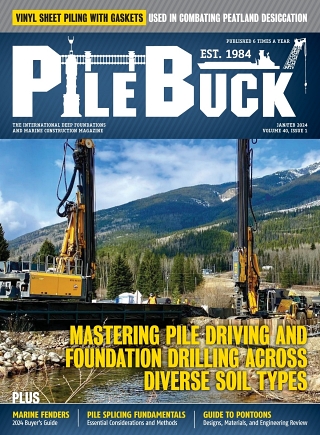


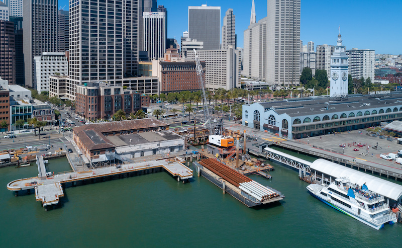
Pier & Wharf Construction Part I: Facility Planning

View the complete version here.
When constructing piers and wharves, the surroundings that support those structures must be taken into account. Some of the factors to consider in the planning stages include location, clearances, operations, landslide approaches, and structural types. By carefully designing these facilities with all of these factors in mind, contractors can ensure the full success of a project.
Location and Orientation
When planning facilities for piers and wharves, consideration must be given to how these structures are aligned and located within a harbor. Factors such as the ease of entering and leaving berths, required quayage, harbor line restrictions, foundation conditions, and isolation requirements all play a role in determining where to locate piers and wharves — and the facilities that support them.
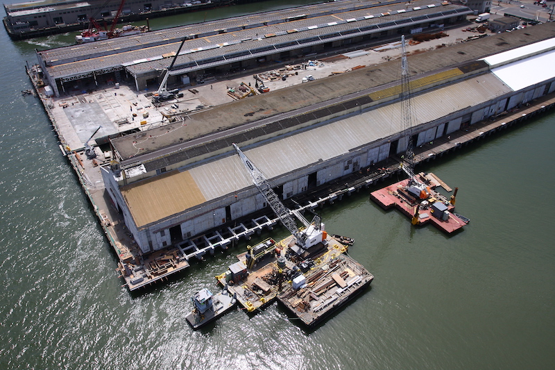
Piers project from the shore into the water, and may or may not be oriented at a perpendicular angle. It can be used on one or both sides, depending on site conditions or the needs of the facility. A slip is the space between two parallel piers or a pier and a wharf. In contrast, a wharf is a structure that is oriented roughly parallel to the shore. Marginal wharves are connected to the shore along their full length, with a retaining structure used to contain upland fill placed behind it. With wharves, ships can only be moored on the outer face. If water depths are insufficient to accommodate deep draft ships close to shore, a wharf — consisting of a platform on piles — is located offshore in deeper water. It is then connected to the shore at one or more points by pile-supported trestles. Ships can be berthed on both sides of these types of wharves. Launches are used for access to wharves.
Initially, piers and wharves should be oriented so that moored ships are facing the direction of prevailing winds and currents. If this is not possible, contractors should examine the possibility of orienting the facility so that winds or currents will hold ships off of the pier or wharf. Otherwise, the berth should be oriented parallel to the direction of the more severe conditions. If there are severe meteorological and hydrological conditions, a single mooring point may be utilized for oil storage terminals, which will allow moored tankers to swing freely. Adequate turning space should be provided so that a ship can be turned before it is docked, and moored with a heading that will allow it to quickly depart as necessary.
Dolphins, which are small independent platforms or groups of piles, can be used on their own or with a pier or wharf for specialized purposes. For example, a mooring dolphin can be used to tie up the bow or stern line of a ship at a more favorable angle. This type of dolphin is usually accessed by a catwalk, and provided with a bollard or capstan. A breasting dolphin can be used for roll-on/roll-off facilities and at fueling terminals where full-length piers or wharves are not required. A turning dolphin is used to guide ships into a berth or away from known obstructions; a mooring dolphin may sometimes be designed to act as a turning dolphin. Finally, approach dolphins can be used to protect the end of a pier or slip requiring protection from incoming ships.
Degaussing/Deperming facilities are an integral part of many piers and wharves. They typically require a magnetic north/south orientation. If both sides of a moored ship must be accessed, two parallel piers with a slip in between them may be preferred for the location of this type of facility.
Dimensions and Clearances
When planning a pier and wharf facility, contractors must analyze the characteristics of the ships to be berthed and understand the support services to be provided in order to determine the dimensions and clearances which will be necessary for a successful facility’s design. For a single-berth facility, the total length of a pier or wharf should be as long as the overall length of the largest ship that will be accommodated, plus 50 feet at each end. For a multi-berth facility, the total length should equal the length of the largest ships that will be accommodated at the same time, plus allowances for 100 feet between ships and 50 feet beyond the outermost moored ships.
Piers and wharves not only provide mooring for ships, but also connect utilities from ships to shore. Fixed utility terminals are generally provided along the bullrail, close to the edge of the pier or wharf. A flexible hose or cable connects to these terminals and then to the ships. These terminals, hoses, and cables may require 10 to 15 feet of space, depending on the type of utility hoods used. This space cannot be used for any other purpose, so careful consideration should be given to the type of utility hood chosen. Electrical docks or substations can be located either on the deck or under deck in watertight concrete vaults. The preference is to locate them under a deck in order to maximize available deck space.
In outfitting/refitting and repair facilities, rail-mounted cranes may be needed for ship fleet load-out. The width needed for these rails will depend on the equipment selected, with the distance from the waterside crane rail to the edge of the pier or wharf being adequate to provide clearance for bollards, cleats, capstans, pit housing outlets, crane power conductors, and other equipment. For supply piers, railroad service may be considered, with standard gage used for trackage. The width of the piers and wharves should be sufficient to allow material-handling equipment and trains to pass, along with allowances for stored cargo and other obstructions.
In addition to tracks for cranes and/or railroads, piers and wharves will generally need to accommodate service trucks and other vehicles. These vehicles are used to move personnel, cargo, containers, and supplies to and from ships. The width of piers must take into account the operation of these vehicles, and provide room for turnarounds. At specified berths, stationary fuel-handling equipment with self-adjusting loading arms to offload fuel products to onshore storage facilities should be provided. The width requirement for these loading arms will depend on the equipment selected.
Generally, pier and wharf decks should not be used for storage sheds and other buildings. However, small buildings to accommodate berthing support and other equipment may be necessary. Similarly, moveable containers and trailers may be temporarily or permanently located on pier decks in order to support the active berthing of ships. Adequate deck space should be provided for locating and accessing these containers and trailers.
Safety should be a top priority for any pier or wharf facility. To that end, a 15-foot-wide unobstructed fire lane should be provided for each pier, independent of net operating width requirements. These lanes should be located and marked near the longitudinal pier centerline. For wharves, a 15-foot-wide unobstructed fire lane should be provided immediately adjacent to the operating area.
The space between each pier, or between a pier and a wharf, should be sufficient to permit the safe docking and undocking of the largest sized ships to be berthed in the slip. The slip should also be large enough to allow for the safe maneuvering and working of tugboats, barges, lighters, and floating cranes. At multiple berth piers, the slips should have adequate clearance to allow the docking and undocking of ships at the inboard berth without interfering with ships at the outboard berth.
The depth of the water in slips will depend on a number of factors. In a sheltered site where the bottom of the slip consists of soft material, the water depth should be equal to the maximum navigational draft of the ships to be accommodated, plus 4 feet. The maximum navigational draft is the distance in feet from the waterline to the keel and below the keel, with the ship in full load condition, taking various projections into account (such as propellers). This prevents grounding or damage to the ship. However, the clearance should be increased if: the harbor bottom consists of a hard material such as rock; there is excessive silting in the harbor; the slip area is exposed to waves, swells, and winds; or extreme low water is 1 foot or more lower than the mean low water level.
To avoid the possibility of overflow, deck elevations should be set above mean high water level at a distance equal to two thirds of the maximum wave height, plus at least 3 feet. Ideally, deck elevation should be set as close as possible to adjacent land in order to allow easy access for mobile cranes, railroads, service vehicles, and personnel vehicles. Ramps may be used to access the decks. If the selected elevation would result in pile caps or beams being submerged either partially or fully, contractors may consider methods of protecting these elements from corrosion.
Operations
On a pier or wharf facility, there are various operations that must be accommodated in order to properly support the ships that are berthed in the slip. These operations may include railroad and crane tracks, mobile cranes, sheds and support buildings, utilities, and light poles.
Railroad and crane tracks are often necessary to allow for the transport of goods and materials to and from ships, and to move cranes more easily onto decks. The number and type of railroad and crane tracks required will depend on the function of the pier or wharf, the ships that will be berthed there, the amount of cargo to be handled, and the rate of cargo transfer.
Railroad tracks should only be considered in stations where most cargo is received by rail. If there are existing railroad networks at the station, installation of tracks should be considered for repair, fitting out, and supply piers and wharves. If tracks are required along the aprons of piers and wharves, at least two tracks should be provided so that one track can be used as a running track while the other is occupied. If locomotive cranes are to be used on piers and wharves, the distance between tracks and curbs should be increased to allow for tail swings of the cranes. When installing crane tracks, the track gage should conform to the gage of existing tracking on adjacent piers and wharves in order to avoid creating “captive” cranes. Finally, for piers and wharves that are primarily used for fueling operations, railroad and crane tracks should not be considered.
In contrast to railroad and crane tracks, all piers and wharves will likely see the use of mobile cranes on deck, except for fueling and degaussing/deperming facilities, where a light-duty mobile crane or forklift truck is often sufficient. These mobile cranes will generally be used to lift light loads of between 5 to 10 tons at a longer reach, which requires high-capacity cranes. If this is not possible in certain areas of the deck, these spaces should be clearly marked and separated by a raised curb. As a general rule, mobile crane operators want to drive as close as possible to the edge of a pier or wharf in order to reduce reach — and this happens to be the best place for locating utility trenches and utilidors. This issue can be resolved by either designing the utility covers so that they can bear the highly concentrated load from a mobile crane (which is typically expensive) or by allowing crane operators to work in dedicated spaces. With some piers and wharves, a two-story system can be designed so that the utilities are kept in the lower level to avoid this issue.
For utilities, connection points should be located and spaced along the pier or wharf edge as close as possible to the assumed berthing positions of the ships that will dock in the slip. The connection points should be carefully located to accommodate any future changes in the berthing plan, or in the type of ships that may be served. The typical utility services provided include fresh water, saltwater, chilled water, hot water, steam, sewer, air, electrical power, communication wiring, and oil and fuel. Utility lines should be kept above deck for ease of access, although transformers and other equipment can be placed below deck in watertight vaults. Storm and sanity sewers that are designed for gravity flow can also be located below deck, as close to the deck as possible. Contractors should be mindful of the fact that any utility lines which are suspended below deck are susceptible to deterioration from exposure, and are more difficult and expensive to inspect and service.
Utility lines located above deck can be accommodated in a number of ways. First, utilidors can be used to protect utility lines. These are protected trenches that run along the waterside edge of a pier or wharf, and are accessible via removable covers from the top. If there are a sufficient number and size of lines, a utility tunnel or gallery can be used, with access from the top or side. However, fuel lines should be kept in a separate trench in order to contain leaks.
Second, ballasted decks — sloping decks filled with crushed rock ballast — allow utility lines to be buried and then topped with concrete or asphalt paving, which provides a working surface for operations. This surface can then be opened up so that the lines can be serviced. Ballasted decks also have the advantage of distributing concentrated loads on the deck slab, which allows for heavier crane outrigger loads.
Third, two-story decks can be used to isolate utility lines in a lower deck, along with galleries that can be accessed from inside of the lower deck. this frees up the upper deck for all other activities and operations.
For the security, safety, and support of nighttime pier activities, both above-pier and under-pier lighting is a necessary consideration. Above-pier lighting can be achieved through a few tall poles that support a battery of light fixtures. These poles require large concrete pedestals, and should be located so as to avoid obstructing pier operations. These fixtures should be sufficiently high and shielded so that the deck and waterside edges are lit up without the lighting blinding a ship’s pilots.
Landside Approaches
To provide access from shores to piers and wharves that are located offshore, landside approaches are often required. These approaches are typically oriented at right angles to the shoreline, with open-type trestle structures that minimize impediments to water flow and disturbances to the shoreline. The volume of the traffic flow, circulation of traffic, existing roads on shoreside, fire lane requirements, and interruption of service due to accidental collision damage will determine the number, width, and orientation of the approaches. The width of the approaches will also depend on the requirements of the utility lines being carried to the pier or wharf. A vehicle or pedestrian approach can often be combined on the same structure unless a large number of personnel are anticipated to need access to the facility. In that case, a separate pedestrian approach may be worth considering.
For facilities that are infrequently accessed, the approach roadway should have a minimum width of 10 feet from curb to curb in order to allow for one-lane vehicular traffic. An additional walkway can be attached to the structure if a higher pedestrian volume is anticipated. For facilities that will be accessed more frequently, a two-way road with a 24-foot-wide curb-to-curb roadway should be provided. Fueling piers and wharves should have a minimum roadway width of 15 feet for clear access of emergency vehicles. If the adjacent land is higher or lower than the pier or wharf, the approach can be sloped up or down to serve as a transition ramp.
Generally, at least two approaches should be provided where volumes of vehicular movement to a pier or wharf facility are large. At multi-berth facilities, approaches every 500 feet or less should be considered. If the pier or wharf is not sufficiently wide to allow for turnarounds, two approaches should be provided so that vehicles can enter and leave without having to turn around. For fueling and degaussing/deperming facilities, at least one single-lane approach structure should be provided. An exception may be made if the facility is built as an island wharf or pier, with access provided by watercraft.
If railroad access is planned, a separate approach is not necessary. However, a pedestrian walkway should be considered for the facility.
When possible, at the intersection of the approach and piers and wharves, additional deck area should be provided in order to allow vehicles to execute turns. For facilities with one-lane approaches, the pier or wharf should have sufficient turnaround space so that outgoing vehicles do not have to back up along the approach. All approaches should provide safety barriers that are adequate for anticipated traffic.
Structural Types
There are three major structural types for piers and wharves: open, solid, and floating. Open piers and wharves are pile-supported platform structures where water is allowed to flow underneath. Solid piers and wharves use retaining structures, such as anchored sheet pile walls, behind which a fill is placed to form the working surface. This prevents the flow of water underneath the pier or wharf. A floating pier has a pontoon structure and is anchored to the seabed through spud piles or tension lines, it being connected to the shore by bridges or ramps. The top can be utilized as a working deck, or a separate working deck supported by columns can be constructed on top of the pontoon. Floating structures are not impacted by tidal fluctuations, but do interrupt the streamflow to some extent. Open and solid piers or wharves can be combined in some situations. However, contractors should avoid combining floating structures with open or solid facilities.
There are many factors that should be considered when determining what structure to construct for a pier or wharf. Each factor should be weighed carefully, alongside of construction and operating costs. The greatest emphasis in any decision should be placed on the type of structure that will withstand adverse meteorological and hydrological conditions, as well as unexpected berthing forces, with another priority being what type will require the least maintenance.
As an initial matter, shoreline preservation should also be evaluated, particularly with regard to the existing aquatic and plant life along the shore of the planned facility. If the area is environmentally sensitive, a solid-type wharf should not be chosen, as it would destroy or disturb a substantial length of shoreline. Instead, an open structure should be selected, as it will have the least impact on the shoreline.
Other environmental considerations include an analysis of tidal or stream prisms, which is the total amount of water flowing into a harbor or stream and out again during a tidal cycle. An open structure should be used if it is necessary to minimize restrictions of a tidal or stream prism. Similarly, along shores where littoral currents transport sand, gravel, and silt, open construction should be used to minimize shoreline erosion and accretion.
Open structures should be used when the facility extends off of an established bulkhead line. This is beyond the limit from which a continuous solid-type construction is permitted.
For areas of high seismic activity, utilizing sheet pile bulkheads or walls should be considered because of the pressures that can develop on the sheet piling. If a pile-supported platform is used along with hydraulic fill, a rock dike should be evaluated for resistance of lateral forces that may occur if the hydraulic fill is liquified. A filter fabric may also be used between the rock dike and the granular fill. In areas of extremely high seismic risk, or where tsunamis and seiches are anticipated, a floating structure should be considered, as it is less likely to be impacted, or will suffer only minor damage from seismic activity.
Open-type structures can be utilized in all water depths, while solid-type structures are limited by the magnitude of the applied surcharge, subsurface conditions, and freeboard of the bulkhead above the low waterline. As a general rule, anchored sheet pile bulkheads can be used in depths of between 30 and 35 feet as long as favorable soil conditions exist. If a solid structure is required in greater water depths, contractors may consider using relieving platforms, bulkheads made of reinforced high-strength steel sheet piles, and cellular construction. If the water is very deep close to the shore and would require very long piles for an open structure, a floating structure — which is unaffected by water depth — may be a more cost-effective option.
Subsurface conditions can also play a factor in the choice of structure type. As a rule, subsurface conditions do not limit the use of open-type construction. The exception is sites where rock is close to a harbor’s bottom surface. In that case, cellular construction may be analyzed as an option. If rock is close to the surface, piles should be appropriately socketed and anchored into the rock. Sheet piling should only be used when the subsurface conditions indicate that suitable anchorage and restraint for the toe of the sheet piling can be achieved, and where the proper material is available for backfill.
Appropriate care should be taken to preventing fill leaching through interlocks when precast concrete and steel sheet pile bulkheads are used in pier and wharf construction. Such leaching can cause subsidence of retained fill. A filter blanket or other method can be installed in order to reduce subsidence and necessary paving maintenance.
When tracks will be mounted on a pier or wharf, such as for a track-mounted crane, a solid-type structure may not be suitable due to its susceptibility to settlement and movement. In these situations, an independent pile-supported track can be utilized to maintain the close tolerance required for rail gage, elevation, and alignment.
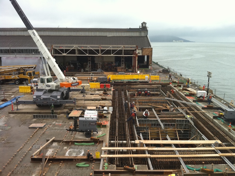
The construction of piers and wharves will depend in large part on what type of structure is being built: open, solid, or floating. The unique aspects of each type of construction should be considered as part of the overall planning phase for the facility.
For open-type structures, the retention of upland fill is an important consideration. To achieve this goal for a platform on piles with a curtain wall at the onshore face, the underwater slope should be as steep as possible, making the pile-supported platform narrow and more cost-efficient. For a platform on a pile with a sheet pile bulkhead at the inshore face, a narrower platform is permitted. However, the bulkhead may cost as much or more than the platform width that it saves.
Solid-type structures can be constructed in one of four ways. First, a sheet pile bulkhead that consists of a flexible wall of steel or concrete sheeting piled with interlocking tongue and groove joints and a cap of steel or concrete can be placed. This bulkhead is anchored above the low water level using systems such as anchor rods and deadman anchors. Second, a sheet pile bulkhead and relieving platform can be used to reduce the lateral load on the sheet piling that is created by heavy surcharges and earth pressures. Lateral restraint is provided by the batter piles that support the relieving platform. Third, reinforced concrete caissons are cast, and then launched and floated to the construction site, where they are sunk into a prepared foundation. From there, the caissons are filled with gravel or rock and a cast-in-place retaining wall is placed from the top of the caisson to the finished grade. Fourth, precast concrete blocks can be used to make a gravity-type wall resting on a prepared bed on the harbor bottom. A fill of granola material is then placed in the back of the wall to reduced lateral earth pressures.
Floating-type structures usually require a flood basin, graving dock, or dry dock in order to be built. These units are constructed and then transported out to the site. This type of construction has the advantage of being able to take place in a part of the country where labor and other costs are more favorable, and then being moved to the construction site.
Finally, hydraulic fill involves drawing soil up by the suction head of a dredge, pumping it with water through a pipe, and then depositing it with water in an area being filled or reclaimed. It is commonly used for land reclamation where land is not available onshore and where dredging is required to provide adequate water deaths for vessels at berths and approach channels. Hydraulic fill may either be of good quality, such as with granular materials, or poor quality, such as with plastic organic silt. When it is used, the structure retaining the fill must be investigated, particularly if the fill is of poor quality. To avoid fill settlement due to loadings from other structures, stabilization of the fill may be required. Hydraulic fill is also susceptible to liquefaction during seismic activity; this factor should be considered before using hydraulic fill.
There are a range of factors that must be considered when designing and planning the facilities for piers and wharves. Constructing these structures requires skilled analysis of tides, water depth, hydrologic conditions, and more. A thorough examination of these issues, as guided by this article, will help to ensure a successful construction project.
View the complete version here.
What factors should be considered when deciding between building a pier or a wharf near shallow waters?
Water depth close to the shore, cost-efficiency, and the need for offshore locations in deeper waters should be evaluated when deciding between building a pier or wharf.
How can a pier or wharf facility accommodate the needs of mobile cranes and other equipment for servicing ships?
The deck space should be designed to allow mobile cranes to back up perpendicular to the bull rail, facilitating maneuvering and ensuring optimal load/reach combinations.