


Crucial Recommendations for Cellular Cofferdams
You can find more in-depth information regarding cofferdams here.
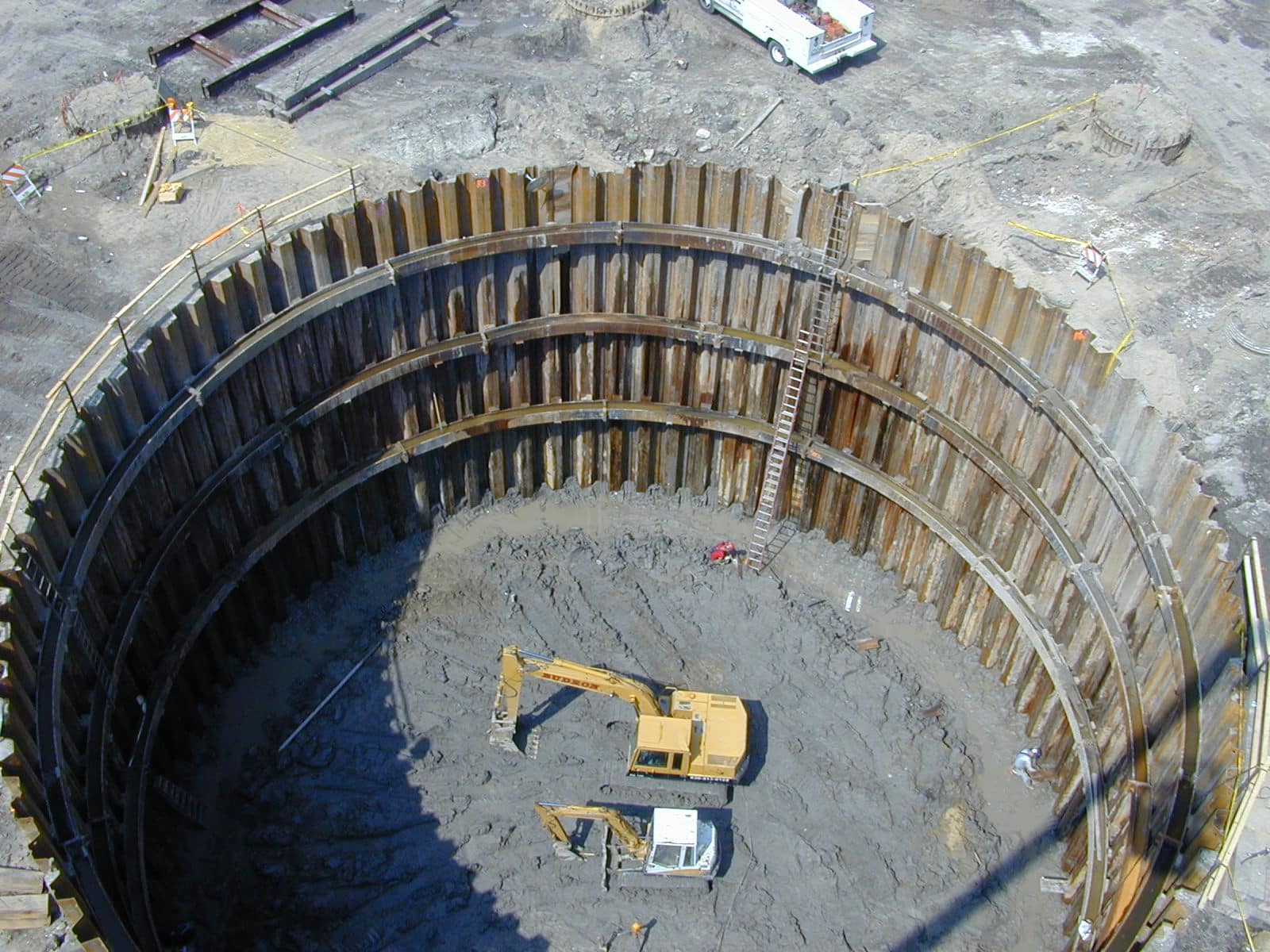
Cellular cofferdams are essential to the construction of dams, locks, wharfs, bridge piers, and other marine structures.
Used to dewater large areas while maintaining a navigation pool, these cofferdams serve as a high or moderately high head dam for an extended time, and also provide a work area which is free from frequent flooding – protecting personnel, completed work, and equipment.
A typical cellular cofferdam is comprised of interconnected cells that form a watertight wall. These cells are filled with soils to provide stability against various lateral forces. Such a wall allows the interior of the cofferdam to be dewatered and for the permanent structure to be constructed in a dry area.
Cofferdam Elements
Cellular cofferdams feature a variety of components that enable them to resist large, differential heads of water.
Height of Protection
The top of the cofferdam should feature a dry working area that can be economically maintained.
When determining the practical range of a cofferdam’s height and establishing a top elevation, consider the following:
- Channel width that will accommodate stream flow and navigation
- Increased flow velocity during high river stages
- Scour that results from high river stages
- Effects the cofferdam has on adjacent structure(s)
- Cell size limitations resulting from interlock stresses and sliding stability
Area of Enclosure
A cofferdam must feature an area sufficient to accommodate access roads, berms, an internal drainage system, and a working area. The need to maintain a minimum channel width or prevent scour will often limit the area to be enclosed by a cofferdam.

Staging
Constructing a cellular cofferdam in a river is done in stages, which allows for flow to continue and navigation to be maintained. Passing water temporarily through completed work and making provisions for a navigable channel comprise the primary stages, which should be limited due to costs and time delays associated with removing and constructing cells. Proper planning will allow some cells to be used for subsequent stages.
Scour Protection
Flowing water can significantly damage a cofferdam cell via scour, which can itself lead to increased under-seepage and interlock stresses. This damage can be limited by fitting the foundation of the cell with riprap or by driving the piling to a depth reaching beneath the anticipated scour.
Deflectors that streamline flow are also effective in reducing scour along the face of a cofferdam. Consisting of curved sheet pile wall, such deflectors extend into the river from the cofferdam’s outer upstream and downstream corners. Hydraulic model studies can aid in developing the most effective deflectors.
Berms
Often constructed inside the cells, a soil berm can provide additional sliding and resistance to overturning, but increasing the diameter of the cells is initially recommended.
Flooding Facilities
Overtopping of a cofferdam can result in significant damage and possible failure, with overflow washing fill materials from cells and eroding berm material.
Before flooding occurs, a cofferdam should be filled with water in a controlled manner by providing sluiceways or floodgates. When using both systems, the adjacent berm must be protected against flow via a concrete flume, splash pad, or heavy stone.
Sluiceways: Featuring a steel pipe placed through a hole cut into the piling of a connecting arc, sluiceways consist of a slide gate or valve that controls flow. The gate or valve is operated from the top of the cell.
Floodgates: Constructed in connecting arcs by cutting the piling at an appropriate elevation, floodgates are controlled by timber needle beams that can be removed when flooding is desired.

Tie-ins
It is imperative that cofferdams be connected to land or a completed portion of a structure being built.
When adjoining a cofferdam to a steep sloping shoreline, the first cell is typically located at a point where its top intersects with the sloping bank. To increase the seepage path and reduce the velocity of water, a single wall of steel sheet piling can be connected to the cell, this extending towards land to form a cut-off wall. The wall should be driven to rock or a specified depth in overburden limited to 30 feet.
In situations where a cofferdam abuts a floodplain lower than the top of the cells, protection from floodwaters can be obtained by constructing an earth dike featuring steel sheet pile cut-off walls.
When tying in to the vertical face of a structure, a section of sheet piling should be embedded in the structure. Tie-ins to a sloping face are more complicated, with the most common solution involving timber bulkheads or timber cribs.
Design
A cellular cofferdam’s design is comparable to an anchored wall; however, because cofferdams consist of steel and soil, a rational design approach is difficult to achieve.
Design and construction of these structures must be accomplished with a high level of engineering competency, as comparable to permanent features of a project.
Most engineers rely on past practice and experience during cofferdam design, with good judgement playing a significant role in decision making. It’s recommended that contractors obtain top professional engineering advice during design stages, and especially in situations where difficult foundations exist. Additionally, it’s important to understand that detailed mathematical evaluations in the hands of inexperienced engineers can equate to misleading and possibly dangerous design conclusions.

Recommendations related to the design, construction, and maintenance of cellular cofferdams are numerous. Some key points to remember include:
- A cofferdam’s design layout should utilize one cell size.
- All design analyses must evaluate the effect of full saturation of the cell fill, unless measures are taken to control the saturation level throughout the cofferdam’s life.
- Riveted or bolted connections with minimum 1/2-inch thick webs are required, as welded connectors have proven unsatisfactory.
- Utilize wye connectors over tees, as the tension in the outstanding leg of the wye connector is less than a tee because the load is applied closer to a tangent.
- Limit the pull on the outstanding leg of connector piles by maintaining a small connecting arc radius, which does not exceed one-half the radius of the main cell.
- When used piling comprises a cofferdam, ensure the sheets are gauged and that they interlock properly. When splicing used sheets, ensure that the sheets are compatible.
- Plug all handling holes in the sheet piling on the loaded side of the cofferdam; this move prevents a significant volume of water from entering the cell and a resulting loss of cell fill.
- Do not drive sheet piling through overburden containing boulders. Particularly dense overburden should be excavated to a maximum depth of 30 feet so that it can be penetrated without damaging the piling.
- If driving is difficult, utilize jetting, but only with extreme caution, as sheet piles have the potential to follow the jetted hole and split out the interlock.
- If fully penetrating the overburden with sheet piles is unachievable, and the possibility of scour by river flow exists, protect the overburden from scour.
- Do not set sheet piling on bare rock, as support from the overburden is key to maintaining the cofferdam’s desired cell configuration.
- When driving piling, ensure the bottom end of a pile does not lead the adjacent pile by more than five feet. Eliminating this possibility reduces the chances of splitting the interlocks.
- Reverse the direction of the pile hammer advance following each pass, as this ensures the piles are driven plumb.
- Drive the first two sheets of the connecting arc adjacent to the main cells prior to filling the cells. Drive and fill the remaining connecting arcs after the adjacent main cells have been driven and filled.
- Require diver inspection of the interlocks after the cells are filled.
- Seal the contact between the sheet piles and concrete whenever cells and fill are placed against stepped or sloped faces of existing concrete. Sealing prevents infiltration of water, which can saturate the fill or cause piping.
- Locate cofferdam cells a sufficient distance from open excavations, protecting the cells from any excavated face instability.

Foundation Treatment
Foundation treatment, in the form of removing objectionable materials, should be considered for all cellular cofferdams that will rest on deficient foundations.
The most common foundation treatment methods include in situ compaction, deep penetration of sheet piling, usages of berms and blankets, foundation material consolidation and grouting. The later method is especially useful in situations where the piling of the cofferdam is driven to rock.
Dewatering
Dewatering a cofferdam is achieved in two phases. The first phase entails dewatering to remove water from the cofferdam’s interior. Dewatering to lower the groundwater represents the second phase, which ensures a dry and stable work area.
A proper dewatering or pressure relief system will intercept seepage that would typically emerge from slopes or the bottom of excavation. This will in turn enhance the stability of the slopes, preventing the loss of materials. It will also reduce lateral loads on cofferdams and improve the backfill characteristics of sandy soils.
Initial Dewatering: Typically, the first 15 feet are dewatered without restrictions, allowing for differential pressure to be developed quickly, which closes the interlocks tightly. After this point, the dewatering rate for large cofferdams is reduced to five feet per day.
Drainage of the cells or connecting arcs must closely follow the dewatering of the cofferdam’s interior. Reserve pumping capacity should be available in preparation for possible mechanical breakdowns.
Foundation Dewatering: Controlling groundwater in the foundation must be attended to throughout construction, with the most commonly used method being the conventional well point system. This type of dewatering is limited to roughly 15 feet of drawdown per stage, and the method is practical for large excavations in the cofferdam basin – namely, where excavation depth doesn’t exceed 40 feet.
Monitoring Instruments
A host of instruments can be utilized to monitor steel sheet pile structures. Any instrument’s accuracy is paramount to the success of monitoring efforts, however, and thus should be verified. Accuracy is best confirmed by monitoring two or more instruments independently or by using a device that can be removed, checked, and recalibrated periodically.
The most common monitoring instruments include:
Observation Wells: Primarily used to measure unconfined groundwater levels, these wells consist of a riser pipe connected to a porous or perforated tip at the lower end. The pipe is installed in a borehole at a specified depth or attached to the sheet pile before driving. These wells are monitored by a probe or tape.
Piezometers: Types of piezometers include open standpipe, diaphragm, closed hydraulic, vibrating wire strain gage, and semiconductor strain gage. These instruments are used to monitor pore pressures in the cell fill and foundation, stabilizing berms and backfill material.
Inclinometers: An inclinometer system comprises a pipe installed in a vertical borehole or attached to the surface of a sheet pile within the cell. These systems monitor horizontal deformation within the cell fill, cell foundation, and stabilizing berm. Inclinometers can also measure deformation along the length of a sheet pile section.
Strain Gages: Mechanical, electrical resistance, and vibrating wire represent the three types of strain gages used to monitor sheet pile structures. Each gage measures small changes in the length of the structural member at the point of installation. These gages can be attached to a surface via epoxy adhesive or welding.
Earth Pressure Measuring Devices: These devices fall into two categories, with one measuring the total stress at a point in an earth mass and the other device monitoring the total stress, or contact stress, against a structural element’s face.
Precise Measurement Systems: This family of instruments is typically used to make alignment, distance, and elevation measurements, and to conduct triangulation and trilateration surveys. These instruments include laser transmitters and receivers, precision theodolites, alignment targets, precision levels, and alignment reflectors.
Cofferdam Importance
With the volume of bridge, dam, and other infrastructure construction slated to rise nationwide in the coming years, a working knowledge of cellular cofferdam elements, design, construction, and maintenance is vital for any marine contractor.
It is imperative to remember that a cofferdam’s design and construction must be on par with and be given the same in-depth engineering focus as permanent structures, as this attention will prevent damage, possible failure, and inevitable project delay.
You can find more in-depth information regarding cofferdams here.
Why is a dry working area on top of a cellular cofferdam crucial, and how is its height determined?
The dry working area atop a cellular cofferdam is essential for economical maintenance, and its height is determined considering factors such as channel width, increased flow velocity, scour effects, and adjacent structure impact.
How can overtopping damage be prevented in a cellular cofferdam, and what are effective methods for controlled flooding?
Overtopping damage prevention involves controlled filling with sluiceways or floodgates; sluiceways feature a steel pipe with a slide gate, while floodgates are controlled by timber needle beams, both requiring protective measures against flooding.