


Pile Guide Part 1 – Load Bearing Piles
View the complete version here.
Introduction
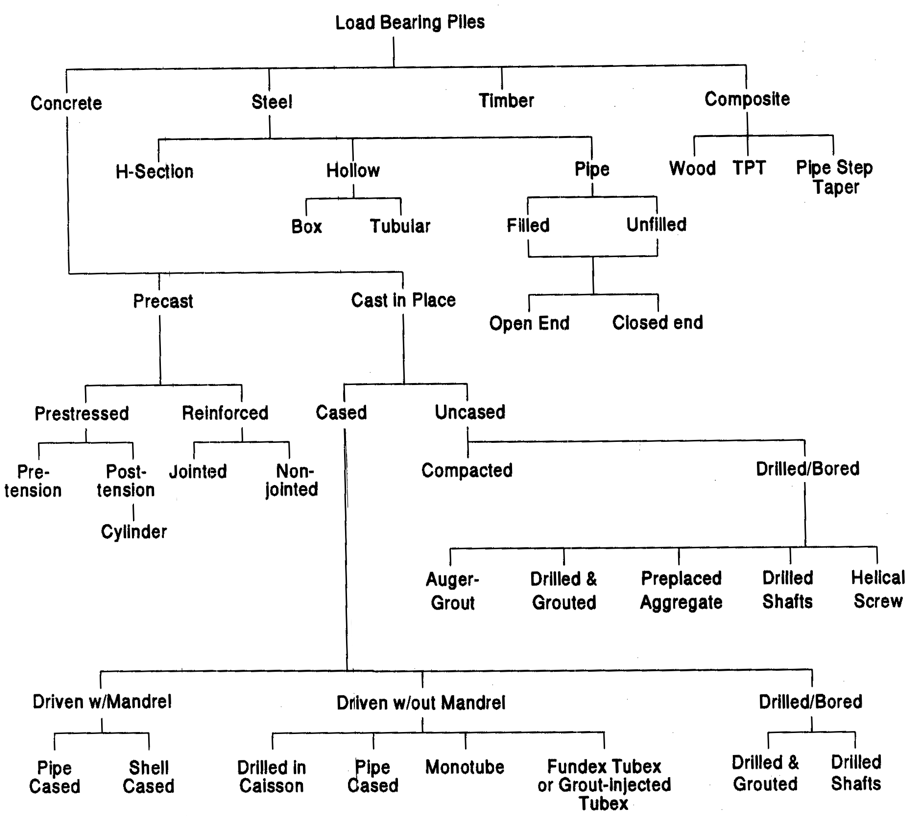
Piles can be categorized in two main types: load bearing piles and sheet piles. There are numerous types of load bearing piles. The below illustration shows a pile classification system based on type of material, configuration, installation technique and equipment used for installation. Load bearing piles can also be classified based on their method of load transfer from the pile to the soil mass. Load transfer can be by friction, toe bearing or a combination.
Steel Piles
General Information:
- Among all piling materials steel piles are allotted the highest allowable unit working stresses, but not necessarily the highest in proportion to the ultimate strength of the material.
- Steel piles are generally considered to be high capacity piles but have been historically used for a wide range of loadings.
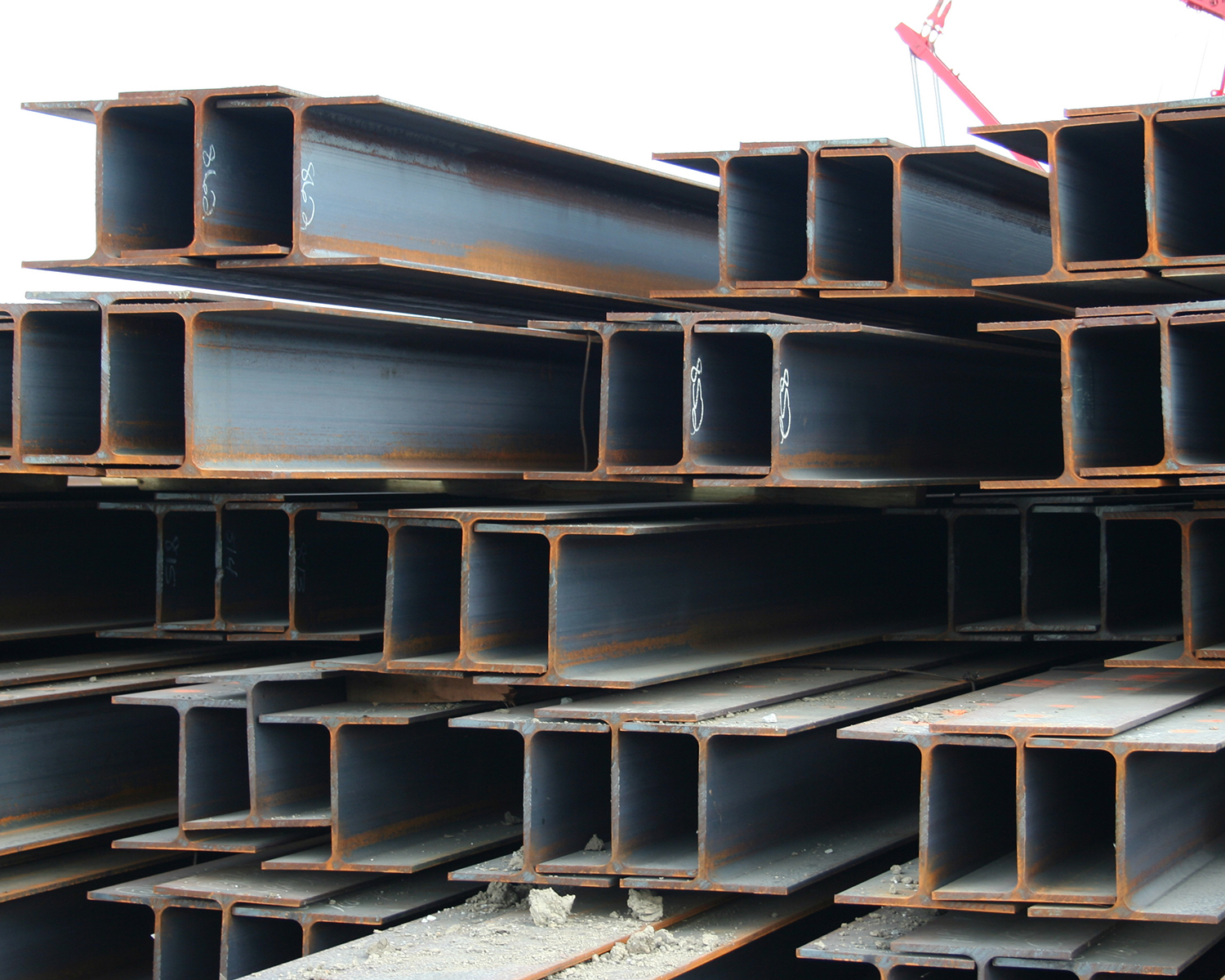
Steel H-Piles
General Information:
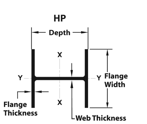
- H-piles are a specially designed sub-group of wide flange shapes with equal thickness in the web and flanges.
- The depth of the section is approximately equal to the width. H-piles are hot rolled from ingots on the same type mill used to manufacture wide flange structural shapes.
- Are versatile and can be used for both friction and end bearing applications.
- Are manufactured as a finished product, which can be driven with standard equipment.
- Can be considered for a design load between 80 kips (356 kN) and 500 kips (2224 kN).
- They function most efficiently for end-bearing or partial end- bearing applications.
- Are a standard in many states for highway bridge piers and abutments where the job sites are remote
Advantages:
- High individual load capacity when driven to bear on or in hard or dense materials.
- Ready availability; can be installed with standard driving equipment; lengths can be easily extended or reduced to the job requirements.
- Compact shape with low displacement – minimum disturbance to adjacent piles or structures; able to penetrate where many other types could not.
- High bending strength for applications involving lateral loads. Readily driven on a batter if required.
- Good tension piles for uplift – constant cross- section, plus steel is best material for tensile strength.
Disadvantages:
- Relatively higher cost unless efficiently loaded.
- Inability to inspect the physical condition after driving (an advantage for closed ended tubular piles)
- Non-constant radius of gyration (an advantage of pipe piles for certain situations).
- Corrosion problems in certain environmental situations if unprotected.
H-Piles as End-Bearing Piles:
- H-piles are most efficient when they can be driven to refusal or practical refusal on rock, or into dense materials overlying rock. The pile functions as a short column, hence the rock may be stronger than the steel for the maximum design load that can be applied.
H-Piles as Friction Piles:
- While many meters of H-piles have been driven for friction applications, they are non-displacement piles and tend to drive further in loose sands and silty sand. There may be good reasons however to select H-piles for this use if, for example, a significant scour depth is computed for a bridge pier abutment.
H-Piles as Soldier Beams:
- One common application of H-piles is their use as soldier beams for retaining walls. These retaining walls can be either permanent or temporary for excavations and braced cuts.
- Typically, the H-piles are driven on 6’ – 8’ (1.8 – 2.4 m) centers in a row with the flanges facing each other. The lagging – either concrete or timber – is then stacked with the ends of the flanges facing the webs. The flanges of the H-piles thus retain the lagging.
- Cross bracing (in the case of braced cuts) or tieback systems can be used to provide additional lateral support for higher walls or loads.
- H-piles also are used in conjunction with sheeting to form high-modulus walls; as discussed in the Pile Buck Sheet Piling Design Manual.
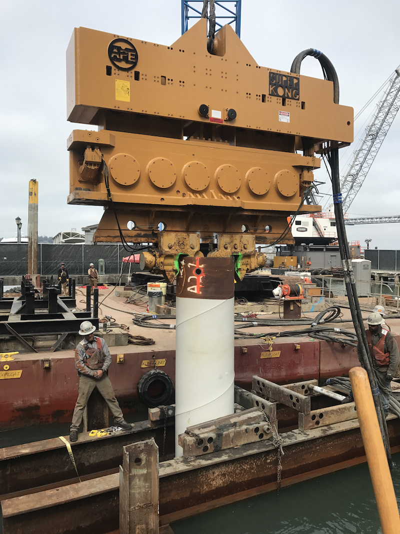
Steel Pipe Piles
General Information:
- Pipe piles usually consist of seamless, welded or spiral welded steel pipes of wall thickness in the range of 0.109” to 2.500” (2.8 – 63.5 mm).
- The piles are available in 8” (203.2 mm) to 48” (1219 mm) diameters.
- Common sizes of pipe piles can be considered for loads between 60 kips (267 kN) to over 400 kips (1779 kN).
- Pipe also provides a strong casing for concrete fill where underground pressures are high.
- Pipe piles may be driven with an open end or a closed end.
Advantages:
- Wide selection of sizes and thicknesses available to choose from.
- Delivery is excellent since there are many manufacturers and distributors; popular sizes are stocked.
- Standard sizes of pipe pile can be driven with conventional driving equipment. Light wall pipe makes an efficient shell for concrete fill when mandrel-driven.
- Pipe piles driven open-end to rock, cleaned, inspected and filled with concrete can resist very high individual loads.
- Pipe piles with wall thickness over about 1/8” (3.2 mm) and filled with concrete are treated as a composite pile with both the steel and the concrete sharing the applied load. The advantages of both steel and concrete are enjoyed.
- Pipe piles can be inspected for material damage and curvature prior to acceptance.
- They can be readily spliced to extend lengths, resist hard driving, and drive straighter because of their constant radius of gyration. They make a more efficient column where unsupported length and large loads are design requirements.
Disadvantages:
- Open-end pipe piles are not as favorable as H-piles for non-displacement applications since the plug of soil inside the pipe also offers resistance to penetration.
- Closed-end they are full displacement piles with certain potential problems associated with displacement.
- They may not be price-competitive with other displacement piles.
Closed Ended Pipe Piles:
- A closed ended pipe pile may be filled with concrete or left unfilled.
- They may be filled with a structural shape such as an H-section in addition to the concrete and socketed into bedrock (rock socketed piles).
- If bearing capacity from the entire pile toe area is required, the pile toe should be closed with a plate or a conical tip.
- Mandrels are usually not used for driving pipe piles, which are generally driven from the pile head.
- When the end of a pipe pile is equipped with a closure device, the pile becomes a displacement pile and functions well as a friction pile particularly in loose sands.
- When driven open or closed end it can also function as a high capacity end-bearing pile.
Open Ended Pipe Piles:
- Open-ended pipe piles are driven when hard driving, caused by the presence of debris, small boulders and the like is anticipated.
- The pipe can be fitted with a special driving shoe, which adds steel thickness at the toe to reduce stresses and damage.
- Open-ended pipe piles may also be partially socketed into rock at site of steeply sloping bedrock or where pile fixity at the toe is a design requirement.
- Pipe piles driven open-end may be filled with concrete after cleaning out the plug, back filled with sand, or the plug ignored.
- This type of pile is also common in the installation of offshore oil platforms, whether driven from the surface or underwater. In these applications, they primarily are designed for uplift loads due to wave or wind action on the structure.
- Open ended pipe piles are recommended where the pile or pile group is to be subjected to horizontal loads and bending moments such as vessel impact and scour on large structures such as bridges.
RR Piles:
- A special type of pipe pile is the RR pile, manufactured by Makela Metals.
- These can be formed into sectional pile systems by mechanical joints.
- They are used as toe-bearing piles in the repair of buildings, as supports under machine bases, and for house foundations.
- Light installation equipment, the cost-effective use of material and versatility of application are benefits offered by RR piles.
- RR piles are spliced using friction joints, so no welding is required for splicing.
Concrete Piles
General Information:
- Concrete piles utilize concrete as the main structural material for compressive loads; however, concrete is deficient in resistance to tensile load. Therefore, when a concrete pile is subject to direct tension or bending, steel must be added to resist these stresses.
- Concrete piles are classified as pre-cast or cast-in- place depending on the method of manufacture. Pre- cast piles are formed in a casting bed, cured, and then driven into place.
Cast-In-Place Concrete Piles
General Information:
- Cast-in-place piles are, as the name implies, cast in a pre-formed excavation at the project site and hence the concrete is not subjected to driving forces.
- In general, cast-in-place concrete piles are installed by placing concrete in an excavated hole in the ground. In some cases the hole is lined with a steel shell or casing which may be temporary or permanent.
- Steel pipe piles, when filled with concrete, can be classified under this category.
- Predetermination of pile lengths is not as critical as for precast concrete piling, since required pile lengths can be easily changed during installation.
- Cast-in-place concrete piles can be installed with or without a mandrel, depending upon the wall thickness of the pile.
Raymond Step Taper Piles
General Information:
- The most popular of the mandrel-driven type piles, consisting of a tapered steel shell to be installed with the aid of an internal mandrel. After withdrawing the mandrel, the shell is then filled with concrete to complete the pile.
Advantages:
- Versatility, a wide range of configurations and variations are possible to accommodate different loads and soil conditions.
- Drivability, the heavy mandrel permits the use of lighter hammers for more effective driving and development of the geotechnical capacity.
- Internal inspection is possible after driving and before concreting.
- Installation is made without damage to the working pile since driving is done on the mandrel and not on the concrete.
- A range of pile capacities is possible from medium to very high.
- Shape characteristics: the configuration is that of a true displacement pile combined with the taper to develop capacity of the soil-pile system in shorter lengths than other types, particularly in loose granular soils.
- The pile shell insures that the hole is secure against soil intrusion.
Disadvantages:
- Displacement piles are particularly vulnerable to pile heave in plastic soils. This condition should be monitored closely.
- Thin gauge shells are vulnerable to damage where underground debris or boulders are encountered.
- Splicing to extend lengths is difficult.
- Shells are vulnerable to collapse from excessive earth or hydrostatic pressure, and special measures must be taken in those situations.
Monotube Piles
General Information:
- Monotube piles are a proprietary pile shell, which is rigid enough to be head driven. The rigidity is obtained by use of heavy gauge steel (3 to 9 gauge), which is longitudinally ribbed or “ fluted” during the cold forming process.
- The basic shell is tapered with tips of about 8” (203.2 mm) diameter and butts 12” (304.8 mm) to 18” (457.2 mm). L
- Lengths range from 10’ (3.05 m) to 75’ (22.9 m).
- Extensions to the tip sections are made with straight-sided tubes up to 40’ (12 m) long.
- After installation, the shell is filled with concrete.
- Monotubes compete with lighter wall pipe piles, and mandrel-driven cast-in-place piles for both friction and end-bearing applications. They are designed assuming both the concrete and steel support the applied load.
Compacted Concrete Piles
General Information:
- The method utilizes a heavy, removable pipe shell and a charge of special mix concrete. Special equipment has been devised to handle the pipe and a heavy drop hammer, which rams the dry- mix concrete into the soil inside the pipe. As the mix descends it pulls the pipe with it.
- When the desired elevation is reached, the pipe is restrained and the concrete mix is pounded out the base where it forms a compact bulb. The pile shell is then rammed in on head of the bulb terminating at the surface.
- This pile is most suited for granular soils and has developed working load capacities of over 300 kips (1334 kN). These piles experience the same general problems as augered piles and they generally are no longer than 40’ (12 m).
Composite Splices
General Information:
- Piles, which combine two types of piles in a single length, are classified as composite piles.
- A very common type of composite pile is a prestressed concrete pile combined with an H-pile “stinger.” This provides both toe protection and penetration assistance for the pile.
- If required a very high capacity composite pile can be formed from a pipe pile that is driven or drilled to rock, cleaned out and socketed into the rock. A steel core section is added and the pipe filled with concrete.
- These piles are quite expensive but some building codes permit very high loads on this pile because of the controlled conditions under which it is installed.
Drilled-In Caissons
General Information:
- Drilled-in Caissons are drilled shafts, which use a driven casing, either permanently or more typically temporarily.
- The caisson can be driven with an impact or vibratory hammer, depending upon the soil conditions.
- Use of a vibratory hammer simplifies removal of the casing.
- Design considerations are the same as those for drilled shafts.
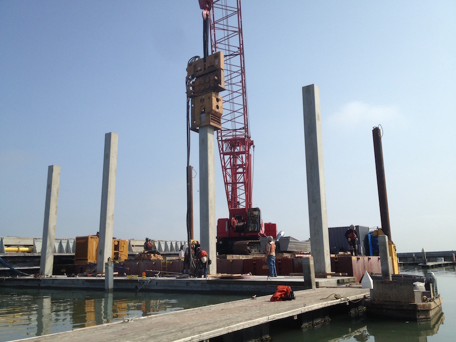
Precast and Prestressed Concrete Piles
General Information:
- Frequently such piles are cast with a hollow core to reduce weight, in which case the head and toe of the pile are solid.
- The hollow core may be used for placing instrumentation during construction or for determining pile damage.
- Precast concrete piles are usually of constant cross section but may have a tapered tip.
- Concrete piles are considered non-corrosive but can be damaged by direct chemical attack (e.g., from organic soil, industrial wastes to organic fills), electrolytic action (chemical or stray direct currents), or oxidation.
- Requirements for precast concrete piles generally apply equally to prestressed units, except reinforcement.
- Such piles must be designed and installed in accordance with the general provisions for piling.
- Precast piles must be proportioned, reinforced, cast, cured, handled and driven to resist the stress induced by handling and driving as well as by structural loads.
- Handling equipment shall be constructed to equalize the reactions on multiple lines of pile pickups.
Reinforced Concrete Piles
General Information:
- These piles are manufactured from concrete and have reinforcement consisting of a steel rebar cage consisting of several longitudinal bars and lateral or tie steel in the form of individual hoops or a spiral.
- Reinforced concrete piles as compared to prestressed piles are more susceptible to damage during handling and driving because of tensile stresses.
- These piles are easier to splice than the prestressed piles and are used where possibilities of variable pile lengths exist.
- These piles are best suited for friction piles in sand, gravel and clays. Typically, the maximum length allowed is 50’.
Prestressed Concrete Piles
General Information:
- This pile consists of a configuration similar to a conventional reinforced concrete pile except the prestressing steel replaces the longitudinal reinforcing steel.
- The prestressing steel may be in the form of strands or wires and is placed in tension.
- The prestressing steel is enclosed in a conventional steel spiral.
- Such piles can usually be made lighter and longer than normally reinforced concrete piles of the same rigidity.
- Pretensioned piles are usually cast full length in permanent casting beds.
- Post-tensioned piles are usually manufactured in sections and assembled and prestressed to the required pile lengths at the manufacturing plant or on the job site.
- The primary advantage of prestressed concrete piles versus conventional reinforced concrete piles is durability.
- Since the concrete is under continuous compression, hairline cracks are kept tightly closed and thus prestressed piles are usually more durable than conventionally reinforced piles.
- Another advantage of prestressing (compression) is that the tensile stresses, which can develop in the concrete under certain driving conditions, are less critical.
- These piles are best suited for friction piles in sand, gravel, and clays.
Prestressed Cylinder Piles
General Information:
- Prestressed cylinder piles are post-tensioned piles that are spun cast in sections, bonded with a plastic joint compound, and then post-tensioned in lengths containing several segments.
- Special concrete is cast by a process unique to cylinder piles that achieves high density and low porosity.
- The pile is virtually impervious to moisture.
- Generally, cylinder piles are used for marine structures or dry land trestles.
- The piles typically extend above ground and are designed to resist a combination of axial and lateral loads.
- They are available in diameters of 36” (914.4 mm) to 90” (2286 mm).
Timber Piles
General Information:
- Two species account for over 90% of the usage—Southern pine and Douglas fir. Southern pine is grown mainly in the southern United States and consists of four sub-species: longleaf, loblolly, slash and short leaf. Douglas fir is a product of the Northwest Coast with the preferred product for piling identified as “Coastal” Douglas fir.
- Some specialty timber is imported from the tropics for marine piling applications. Greenheart, imported from South America, is one such species. It features high strength and superior resistance to decay and to attack by marine borer organisms.
- Timber piles are processed as clean-peeled (all outer bark and 80% of inner bark removed) rough peeled (all outer bark removed) and un-peeled (all bark retained). Piles that are to be further treated with preservatives must be clean-peeled.
- Timber piles are frequently installed un-peeled and untreated. These are generally for use in temporary structures or installations with a planned short-service life. However, the majority of timber piles are now treated with wood preserving chemicals to extend their life.
- Sawed timbers are very rarely used for piling, therefore timber piles are always round and tapered, which is an efficient shape for a pile.
Quality:
- Timber for piling should be of sound wood and free from decay and insect damage. Other possible defects are identified as follows:
- A check is a separation of the wood extending across the growth rings from the surface toward the centre but not completely across the section. A check should not extend any further than the pitch (centre core).
- A shake is a circumferential separation of the rings of growth. The lengths of shakes in the head of the pile are limited.
- A split is a lengthwise separation of the wood across the growth rings but extending from one surface to the other. Splits may not be any longer than the diameter of the head.
- Knots are, of course, the source of limbs, which have been trimmed from the trunk. Restrictions are imposed on the sizes and depth of knots based on being classed as “sound” or “unsound.”
- Straightness requires that a straight line from center of head to center of toe must lie entirely within the pile body.
Advantages:
- Low cost, per ton of capacity.
- Dependable, renewable supply – available in a range of lengths and sizes.
- Long history of successful application to low and medium unit loads.
- Easily handled and driven with conventional equipment.
- Tapered shape and full displacement characteristics advantageous for developing soil capacity in shorter lengths.
- Strength in tension and bending applications.
Disadvantages:
- Cannot be spliced to extend lengths.
- More vulnerable to driving damage.
- Vulnerable to deterioration from a number of natural sources unless effective protection is provided.
- Restrictive properties regarding strength, sizes and lengths.
View the complete version here.
What is the typical wall thickness of steel pipes?
Pipe piles usually consist of seamless, welded or spiral welded steel pipes of wall thickness in the range of 0.109” to 2.500” (2.8 – 63.5 mm).
When do you use compacted concrete piles?
Compacted concrete pile is most suited for granular soils and has developed working load capacities of over 300 kips (1334 kN). These piles experience the same general problems as augered piles and they generally are no longer than 40’ (12 m).