Soil Mechanics Guide Part II

View the complete article here.
Presentation of Geotechnical Information
You will compile all the data collected from the subsurface investigation and analysis into a geotechnical report. The purpose of the report is to present the data collected in a clear manner. The format and contents of the geotechnical report are somewhat dependent on the type of project. Most projects will generally require either a roadway soil survey or a structure related foundation investigation, or both. This information is critical to the design, construction, and service life of the project. It becomes the permanent record of all pertinent information upon which geotechnical-related conclusions and recommendations are made for the project.
For reports prepared by consultants the consultant’s recommendations should be documented and retained. The department’s final decision should be documented separately (i.e. in letter form to the structures engineer in charge of the project).
This section describes the format for presentation of geotechnical data for each type of project. General topics addressed in the geotechnical report are outlined below. Not every project will follow these formats exactly. Some items may be unnecessary; other items will need to be added. We will also discuss the finalization and distribution of the geotechnical report and incorporation of its recommendations into the design.
Roadway Soil Survey
The geotechnical report for a roadway soil survey presents conclusions and recommendations concerning the suitability of in-situ materials for use as embankment materials. Special problems affecting roadway design, such as slope stability or excessive settlement may also be discussed. The following is a general outline of the topics to include in the report.
General Information
- List of information provided to the geotechnical consultant (alignment, foundation layout, 30% plans, scour estimate, etc.).
- Description of the project, including location, type, and any design assumptions.
- Description of significant geologic and topographic features of the site.
- Description of width, composition, and condition of existing roadway.
- Description of methods used during the subsurface explorations, in-situ testing, and laboratory
- Soil conservation (SCS/USDA) and USGS maps.
Conclusion and Recommendations
- Explanation of stratification of in-situ materials including ground water table.
- Evaluation of strength and extent of unsuitable soils within the proposed alignment including their probable effect on roadway performance. The extent of removal of the unsuitable material should be Recommendations for special construction considerations, which minimize anticipated problems should be included.
- Recommended design LBR based on the most conservative value from either the 90% Method or the + 2% of Optimum LBR Method.
- Estimated soil drainage characteristics and permeability or infiltration rates. In the case of rigid pavement design, include average laboratory permeability values for each stratum.
- Recommendations for cut or fill sections when seepage, stability or settlements are significant.
- Recommendations for any cast-in-place or MSE walls.
- Any storm water retention pond considerations.
- Effect of roadway construction (vibratory rollers, utility excavations, etc.) on surrounding structures and effect on the usage of the structures during roadway construction.
Roadway Soils Survey Sheet
This sheet presents a material description and results of classification and corrosivity tests for each stratum. Recommendations for material utilization are provided. Visual classification of muck is not sufficient; include organic content test results in the material description. Include the number of lab tests runs for each stratum for corrosion and classification test results. Include the range of values of all tests performed for each stratum. The report of test results sheet is included in the construction plans. Figure 4 is an example of a typical test results sheet.
Roadway Cross Sections
Simplified boring logs are plotted on the cross-section sheets included in the construction plans. Each material stratum is numbered corresponding to the strata on the test results sheet.
If cross sections sheets are prepared by others, include the appropriate subsurface information. It is the geotechnical engineer’s responsibility to verify that the data is correctly incorporated. Indicate removal of unsuitable materials on the cross sections.
Structures Investigation
Introduction
The geotechnical report for a structure presents the conclusions and recommendations for the most suitable foundation types. It also presents information required for incorporating such foundations into the design of the structure. Recommendations for related work, such as approach embankments and retaining walls, are also included. Special construction considerations are noted. Special provisions should only be used for site-specific items. The following is a general guide to the contents of a typical structure foundation report.
Scope of Investigation
- Description of type of project, location of project, and any assumptions related to the project.
- Vicinity map, including potentiometric map, USGS and soil survey maps (SCS/USDA), depicting project location.
- Summary of general content of report.
Interpretation of Subsurface Conditions
- Description of the methods used in the field investigation, including the types and frequencies of all in-situ tests.
- Description of the laboratory-testing phase, including any special test methods employed.
- Boring location plan and plots of boring logs and cone soundings. Note the size of rock core sampled, and the minimum acceptable rock core diameter to be used should be 2.4 inch (61 mm) (although 4 inch {101.6 mm} diameter rock cores are preferable). See Figure 4-6 and Figure 4-7 for examples of report of core borings and report of cone soundings sheets. These sheets are included in the final plans. Standard soil type symbols used in plotting the borings are shown in Figure 4-8.
- Estimated depths of scour used, if applicable.
- Environmental class for both substructure and superstructure, based on results of corrosivity tests. This information is also reported on the report of core borings sheet. For extremely aggressive classification note what parameter placed it in that category.
- Summary table of soil parameters determined from field and laboratory testing.
- Table of soil parameters to use with computer modeling. These parameters can be broken up into zones across the bridge length.
- MSE or cast-in-place wall recommendations.
Existing Structures Survey and Evaluation
Early in the design phase, the potential damage to structures in close proximity to construction activities should be evaluated. Include the usage of these structures in the evaluation. Vibration, settlement, noise, and any other damaging results of these construction activities should be considered in the evaluation. When warranted, the recommendations should include possible means of reducing the damaging effects of the construction activity. Recommendations such as time restraints on certain operations, underpinning, monitoring, or even purchasing of the property.
Include each structure’s address, type of construction, the estimated vibration level that may cause damage, the usage (storage building, hospital, etc.), the potential problem, and the recommended actions to minimize the impact.
Typical Notes
- Noise Restrictions: The contractor should strictly adhere to all local noise ordinances. All pile driving operations should be limited to the hours of 7:00 am to 6:00 pm. Methods of maintaining construction noise levels may include but not be limited to temporary noise barriers, enclosures for equipment, mufflers, etc. There will be no separate payment for any of these measures.
- Vibration: The contractor should provide surveys and settlement/vibration monitoring of the existing structures listed.
Structure Foundation Analysis and Recommendations
Provide alternate foundation recommendations for all structures including recommendations for spread footings, driven piles, and drilled shafts. Include an explanation for any of these alternates judged not to be feasible. Summarize the types of analyses performed.
Spread Footings
- Reason(s) for selections and exclusions.
- Elevation of bottom of footing or depth to competent bearing material.
- Allowable soil pressure based on settlement and bearing capacity.
- Settlement potential.
- Recommendation for special provisions for footing construction, including compaction requirements and the need for particular construction methods such as dewatering or proof rolling.
- Sinkhole potential.
- Soil improvement method(s).
Driven Piles
- Suitable pile types and reasons for design selections and exclusions.
- Plots of soil resistance for selected pile size alternates.
- Recommendations for minimum pile length or bearing elevation (non-lateral).
- Minimum pile spacing should be at least three times the diameter/width of the pile size used.
- Estimated pile settlement or pile group settlement, if significant.
- Effects of scour, downdrag, and lateral squeeze, if applicable.
- Maximum driving resistance to be encountered in reaching the estimated bearing elevation. Capacity analyses may have included the estimated scour of substantial amounts of materials. The presence of this material during driving will contribute added resistance to driving.
- Recommended locations of test piles and pile installation criteria for dynamic monitoring.
- Selection of load test types, locations and depths where applicable. For static, Statnamic or Osterberg load testing the ultimate load the test should be taken to must be shown in the plans.
- Recommendations for special provisions for pile installation (special needs or restrictions). Special construction techniques may be needed to minimize the effects of foundation installation.
- Present recommendations for information to be placed in the pile installation table when applicable.
- Present soil parameters to be used for lateral analysis accounting for installation techniques and scour. The geotechnical engineer should check the final lateral load analysis for correct soil property
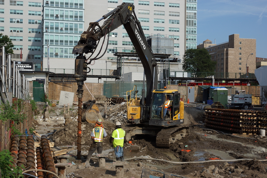
Drilled Shafts
- Include plots of soil resistance versus elevation for selected alternate shaft sizes.
- Recommendations for minimum shaft length or bearing elevation, for shaft diameter, and design soil resistance. The minimum socket length should be indicated, if applicable (non-lateral).
- Minimum shaft spacing or influence of group effects on capacity.
- Effects of scour, downdrag, and lateral squeeze, if any.
- Estimated drilled shaft settlement or shaft group settlement.
- Recommended locations of Selection of load test types, locations and depths. For static, Statnamic or Osterberg load testing the ultimate load the test should be taken to must be shown in the plans.
- Recommendations for special provisions for shaft installation (special needs or restrictions). Special construction techniques may be needed to minimize the effects of foundation installation.
- Present recommendations for information to be placed in the drilled shaft installation table.
- Include the potentiometric surface map information.
- Present soil parameters to be used for lateral analysis accounting for installation techniques and scour. The geotechnical engineer should check the final lateral load analysis for correct soil property
Approach Embankments Considerations
Settlement
- Estimated magnitude and rate of settlement.
- Evaluation of possible alternatives if magnitude or time required for settlement is excessive and recommended treatment based on economic analysis, time and environmental constraints.
Stability
- Estimated factor of safety.
- Evaluation of possible treatment alternatives if factor of safety is too low. Recommended treatment based on economic analysis, time and environmental constraints.
Construction Considerations
- Special fill requirements and drainage at abutment walls.
- Construction monitoring program.
- Recommendations for special provisions for embankment construction.
Retaining Walls and Seawalls
- Recommended wall type.
- Recommended lateral earth pressure parameters.
- Factored soil resistance or alternate foundation recommendations.
- Settlement potential.
- Factored soil resistance and loads with respect to sliding and overturning (including standard index wall designs).
- Overall stability of walls.
- Recommendations for special provisions for fill material (except MSE walls), drainage.
- Special considerations for tiebacks, geotextiles, reinforcing materials, etc., if applicable.
- MSE reinforcement lengths required for external stability, if applicable.
Steepened Slopes
- Estimated factor of safety for internal and external stability.
- Spacings and lengths of reinforcement to provide a stable slope.
- Design parameters for reinforcement (allowable strength, durability criteria, and soil-reinforcement interaction).
- Fill material properties.
- Special drainage considerations (subsurface and surface water runoff control).
Appendix
All structure investigation reports should include an appendix, which contains the following information.
- Report of Core Boring Sheets.
- Report of Cone Sounding Sheet.
- Data logs or reports from specialized field tests.
- Laboratory test data sheets. The following are examples of what should be provided.
- Rock Cores: Location, elevation, Maximum Load, Core Length, Core Diameter, Moist Density, Dry Density, Split Tensile Strength, Unconfined Compressive Strength and Strain at Failure.
- Gradations: Location, elevation, test results.
- Corrosion Tests: Location, elevation, test results.
- Engineering analyses and notes.
- FHWA checklist (if applicable).
- Any other pertinent information.
Final or Supplementary Report
A successful field investigation depends on communication between the geotechnical, project design engineer, and construction engineers throughout the duration of the project. It is best if the input form the geotechnical engineer is incorporated as the project develops.
Often, the initial geotechnical report is considered preliminary. It may be necessary to modify geotechnical recommendations as the design of the project progresses. When the project approaches the final design stage, the geotechnical engineer should prepare a final or supplementary report to revise (or confirm) assumptions and recommendations that align with the final design plans. Include the following topics in this report.
- Final recommended foundation type and alternates.
- Size and bearing elevation of footing or size, length, and number of piles or drilled shafts at each structural foundation unit.
- Final factored design loads.
- Requirements for construction control for foundation installation.
- Possible construction problems, such as adjacent structures, and recommended solutions.
If revisions to the preliminary report are not necessary, submit a letter stating that the initial report is final.
Signing and Sealing
A professional engineer should sign and seal geotechnical documents in accordance with local professional engineering laws and regulations. For supplemental specifications and special provisions, which cover other topics in addition to geotechnical engineering, the engineer in charge of the geotechnical portions should indicate the applicable pages. The engineer signs and dates originals of the sheets for plans within the space designated “Approved By”. One record set of full-sized prints should be signed, sealed, and dated.
Plan and Specification Review
In addition to writing a report, the geotechnical engineer should review all phases of the plans and specifications to ensure that the geotechnical recommendations have been incorporated correctly.
What Not to Include in Your Report
Some of the things undesirable in a report are:
- Specifications. Reference each specification by number or section number.
- Unjustified changes. Changes to the specification without valid justification.
- Long verbal descriptions. Use a simple table instead.
More Than a Report
The information gathered in a field exploration is the backbone of a construction project. Without it, the project manager risks placing a structure on a poor foundation. Surrounding buildings could be damaged – costing the company untold amounts of money to repair. In some cases, lives are literally at stake. Accurate testing and note taking, careful handling of samples, and communication with all project engineers will ensure a successful outcome.
What information is included in a geotechnical report, and why is it essential for construction projects?
A geotechnical report compiles data from subsurface investigations, providing critical insights for construction design, stability, and service life, influencing decisions on foundation types, materials, and potential challenges.
How does a geotechnical engineer contribute to project development, and what is the significance of a final or supplementary geotechnical report?
Geotechnical engineers contribute by assessing subsurface conditions, recommending foundation types, and providing construction control requirements; a final or supplementary report ensures that geotechnical recommendations align with the project's final design plans, addressing issues such as foundation types, loads, and construction control.

