


Placement and Design of Concrete in Drilled Shaft Construction: Part 1

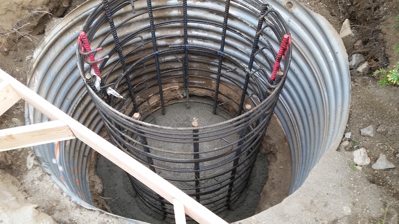
Constructing a drilled shaft foundation involves fabricating a reinforced concrete structure in position. It is often an exceptionally challenging task, particularly when the job requires the concrete to be placed and reinforced underwater at depths exceeding 100 feet below the ground surface. Given the necessity of a solid foundation for a drilled shaft, concrete placement techniques and materials are a critical aspect of the process, requiring careful planning and design. The mix design, means and method of concrete placement are typically delegated to contractors, which requires a solid understanding of the characteristics of drilled shaft concrete.
In this article, we will cover the placement of concrete for drilled shafts, as well as the design and testing of concrete mixes. Given the unique requirements of drilled shaft concrete, we will focus on the issues that are critical to drilled shaft construction and performance.
Basic Characteristics of Drilled Shaft Concrete
Given the specific construction techniques required for drilled shafts, concrete used in this type of project must be designed to meet the requirements of the application. The workability of the concrete during transport and placement operations is the single most important factor, as the mix must often be transported long distances to a remote site, pumped a long distance, and then flow readily through a tremie and congested reinforcement under slurry to fill a hole at depths exceeding 100 feet. In addition, the mix may be required to remain fluid for periods of 4 to 8 hours or more in varying ambient temperature conditions. It also must be able to consolidate under its own self weight without vibration, segregation, excessive bleeding, or heat of hydration. This can make obtaining the proper mixture of concrete challenging for drilled shaft construction.
There are 9 basic characteristics of concrete that must be met for drilled shaft construction: filling ability, passing ability, self-weight compaction, resistance to segregation and bleeding, resistance to leaching, controlled setting, durability, low heat of hydration and appropriate strength and stiffness. Generally, drilled shafts are not subjected to high structural stresses within the concrete. As such, the strength demands are ordinary compared to the high degree of workability required of the concrete.
First, the concrete must have sufficient filling ability — that is, the ability to flow readily through the tremie to fill the shaft excavation and restore the lateral stress against the sides of the borehole. Second, the concrete must have passing ability, which means that it must be able to pass through a reinforcement without blocking. To do so, the aggregate size and gradation must be proportion can pass through small openings without blocking.
Third, the concrete must have self-weight compaction, or the ability to fill and consolidate under self weight. This is required because vibration of concrete in a borehole is either not possible or desirable. Fourth, the concrete must have resistance to segregation and bleeding, so that both the coarse aggregate particles and the water are evenly distributed in the mix. Fifth, the concrete should have resistance to leaching so that it is resistant to mixing with external fluid and leaching when it is placed under a drilling fluid. Sixth, it should maintain a controlled setting so that it retains its workability through the time required for completion of placement operations.
Seventh, the concrete must be durable to minimize the potential for corrosion, particularly for the concrete cover on the reinforcement. Eighth, the concrete should have low heat of hydration, so that certain conditions (such as hot weather concrete operations or high volume concrete placement) do not lead to delayed ettringite formation or thermal cracking. Ninth, the concrete must have appropriate strength and stiffness to meet the structural performance requirements.
Placement of Concrete
In order to meet the requirements of a drilled shaft construction project, concrete placement must be carefully planned and executed. Special consideration should be paid to concrete placement in dry and wet excavations, particularly if temporary casing is to be used, as described below.
Dry Shaft Excavation
The simplest type of concrete placement in drilled shaft construction is a dry excavation without removable casing. Generally, concrete can be placed using free fall methods provided that the concrete is directed through the center of the shaft without hitting the reinforcing cage or sides of the hole, which could cause distortion of the cage, segregation of the concrete, or soil/debris in the concrete.
In this type of placement, the flow of the concrete should be directed to the center of the borehole and cage using a drop chute or other device to keep the stream centered in the hole. In constructing a drop chute, relatively stiff or rigid pipe should be used, as it can be difficult to direct the discharge from a flexible hose. A tremie pipe may also be used as a simple drop chute in a dry shaft excavation.
Studies have demonstrated that free fall placement of concrete does not impact the compressive strength of the concrete. It also does not result in any observable segregation of the mix. In one study, results suggested that free-fallen concrete drove out air, produced denser concrete, and actually produced stronger concrete. Given this research, it appears that concrete can be dropped freely at distances of up to 80 feet without issue, as long as the mix does not strike the cage or borehole wall.
Importantly, if the shaft excavation is not completely dry and the concrete is placed using a free fall method, the concrete will mix with water at the base of the shaft, resulting in concrete mixing with excessive water or a zone of washed aggregate. To resolve this issue, contractors can pump out water so that less than 3 inches of water (depth) remains, provided that there is not a substantial inflow of water. However, if excessive seepage occurs, it will be necessary to place the concrete using a wet method, as describe below.
Dry Shaft Excavation within a Cased Hole
In some situations, a dry shaft excavation is achieved through the use of temporary casing. This requires some additional considerations in the placement of concrete, particularly with regard to removal of the casing.
If temporary casing has been used to seal a dry shaft excavation, there is often an accumulation of fluid on the outside of the casing. When the casing seal is broken in order to remove it, the head of the concrete inside of the casing must be at a sufficient level to withstand the fluid pressure outside of the casing. The head of the concrete within the casing will drop as the concrete flows to fill the annular space and any other voids. To allow for this flow, contractors should maintain a margin of excess head above the computed head.
The need to provide enough concrete to overcome external fluid pressure is made more complex by the fact that there could be over break or cavities of unknown side outside of the casing. As the casing is pulled, the head of the concrete will immediately drop. Concrete must therefore be supplied at a rate that is sufficient to maintain a positive pressure head of concrete inside of the casing in excess of the fluid pressure head to the ground surface outside of the casing.
In placing concrete in dry shafts with temporary casings, the concrete must have good workability throughout the process. The mix must flow easily through the cage in order to displace fluids and completely fill the excavation. A loss of workability prior to extraction of the casing could result in arching within the casing, leading to the concrete lifting and a “neck” occurring below the casing. In addition, concrete that does not flow readily through reinforcing will often load the cage vertically and may cause racking or distortion in the cage.
If telescoping casing is used, concrete should fill from the bottom up as each section is removed. The concrete should fill from the inside out, with the casing extraction carefully managed to prevent water from being trapped within the concrete.
Wet Excavation
If a wet exaction is required, concrete must be placed underwater using either a tremie or a pumpline. In both cases, the concrete must have good workability during placement operations. In addition, the bottom of the concrete delivery tube must be maintained at a sufficient depth below the rising surface of fresh concrete. Gravity tremies are more commonly used in drilled shaft construction, particularly in relatively deep shafts.
A gravity-fed tremie is a steel tube that is fed from a pump or through discharging from a bucket or a ready mix truck. There is typically a hopper on the top of the steel tube. Steel is the preferred material for the tube, as aluminum will react with the concrete, and plastic piping is not strong enough to handle the mixture. The diameter of the tube will depend on the depth and diameter of the excavation. Generally, tremie pipes with an inside diameter of 8 to 12 inches are the most common.
To prevent inflow of slurry during concrete placement, the tremie must be watertight, and must have a smooth and clean inner surface to minimize drag on the flow of the concrete. A smooth outer surface will help to avoid entanglements with the reinforcing cage. For relatively short shafts (of 40 to 50 feet or less), a solid, one-piece steel tube may be used as a tremie. For deeper drilled shafts, a sectional or segmented tremie will likely be required, with waterproof joints.
Given the presence of water or slurry, the concrete flow must be controlled so that there is a minimal amount of contamination. This can be achieved through the use of a closed tremie, which involves sealing the bottom of a tremie with a covered plate, or with an open tremie, where a traveling plug is inserted ahead of the concrete.
With a closed tremie, the pipe is placed into the shaft, then the concrete is placed into the tremie. Once the concrete is in the tube, the tremie is opened to release the concrete. The closed tremie must be watertight to avoid contamination, and should be visually checked for leaks before concrete placement. Buoyancy can be an issue with closed tremie tubes, which may require adding weights to make it sufficiently heavy. The seal is achieve with a simple steel closure plate, often closed with a rubber gasket, duct tape or plastic wrap. Other designs may include a hat-like device, or a hinge system that attaches the plate to the tremie.
As the concrete fills the tremie tube, the tremie is lifted, breaking away the closure plate and producing a surge of concrete. This rush of concrete forces its way under the fluid at the base of the excavation and pushes the drilling fluid out at the top. It is important that the closure plate release freely when the tremie is lifted, so care should be taken that the plate is not attached too solidly to the tremie.
With an open tremie, an open tube is installed into the slurry or water, and held a few inches from the bottom of the excavation. A traveling plug (often referred to as a “pig” or a “rabbit”) is then placed into the tremie pipe to prevent the concrete from mixing with the fluid. This plug is typically saturated with water, and should be able to withstand the pressure to perform as a separator.
The tremie pipe must be kept within a few inches of the bottom of the shaft until a head of at least 10 feet of concrete is achieved in the drilled shaft above the tip of the tremie. This prevents the concrete from mixing with the water or slurry and contaminating the concrete. During tremie placement, it is recommended that the end of the tremie be placed t least 10 feet into the fresh concrete. As the concrete rises, the tremie should be lifted to maintain flow. Provided that the concrete has good workability, it may be possible to maintain tremie embedment of 20 feet or more. However, this may cause the reinforcing cage to start to lift along with the column of concrete.
If the concrete starts to lose workability, it will fill the tremie without emptying. Workings may attempt to shake the tube up and down or side to side to get the concrete flowing. Tis may help to re-establish flow, but it can also make a vent alongside the tremie pipe and trap laitance or sediment on top of the concrete. The better solution is to adjust the mix characteristics.
Another option for wet placement is to use a concrete pump with a tremie. In this system, the pump line is a rigid shell pipe, typically 4 to 6 inches in diameter, that is connected to the delivery line via a short section of flexible hose. An advantage to this system is that unlike with gravity-fed tremie tubes, a crane can lift the pump line system as needed to direct the flow and manage the operation.
In a closed pump tremie, rigid tremie pipes are preferred to keep the line close to the bottom of the excavation and to control the initiation of the concrete flow. As with gravity-fed tremie pipes, a pumped tremie line should have a minimum 10 foot embedment. However, the line should be lifted as the column of concrete within the shaft rises.
The concrete used with a pump line system should have similar workability characteristics as used in gravity tremie placements. If the concrete loses workability, the pressure behind the pump line will make the pipe push up and out of the concrete, causing defects in the concrete.
Even if tremie operations are conducted perfectly and the concrete mixture is properly designed, the concrete may still be defective if the hole is not clean or if the slurry is full of sand. For this reason, the base of the shaft must be reasonably free of loose debris, which can be stirred up by the initial discharge of concrete. Similarly, the sand content of the slurry should be observed to ensure that sand is not enveloped in pockets in the concrete, weakening the drilled shaft construction.
Records of Concrete Volume During Placement
During concrete placement, contractors should measure and record the volume of concrete placed as a function of elevation in shaft. This can typically be determined using a simple weighted tape. These measurements can help to identify areas where over break may have occurred, or where concrete may be filling voids. This can allow for further investigation into conditions that may warrant additional work.
The most common way to obtain accurate measurements of concrete volume is to utilize truck tickets, with the volume of concrete in the tremie or pump lines estimated and subtracted from the total. If there is a stroke counter on a pump, it may be used to estimate volume pumped, but only if the volume per stroke is calibrated. Similarly, if a bucket with a known volume is used to place concrete, an approximate value of concrete placed can be determined.
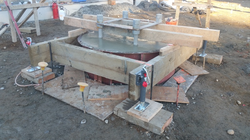
Completion of Concrete Placement at Shaft Head
After concrete placement has been completed in drilled shaft excavation, there is often several feet of contaminated concrete that will need to be removed. If the top of the shaft is at or near ground level, this concrete can be shoveled off by workers until clean concrete is revealed. Otherwise, the contractor may be forced to remove the contaminated material after the concrete hardens, typically using jackhammers.
Drilling Near a Recently Concreted Shaft
After concrete in a drilled shaft has been poured, it must achieve an initial set before drilling or casing installation can be done in the vicinity. For these purposes, vicinity is defined as a clear spacing of three shaft diameters. This will prevent communication between the nearby excavations, where the fluid pressure of fresh concrete breaks through to nearby excavation. The danger of this occurring may be particularly acute in a karstic region. Normal drilled shaft construction operations do not generally cause structural damage to concrete. However, there is evidence that vibro-driving of casing may lead to excessive bleed water or instability of the fluid concrete-filled shaft.
Typical concrete mixes used for drilled shafts should achieve a set within 24 hours. However, exceptionally long placement times may require a concrete mixture with a high dosage of hydration control admixtures. This could extend this 24 hour limit. The use of silica fume or other admixtures could shorten the 24 hour window, but using high-early-strength concrete is not recommended for shafts of greater than 5 feet in diameter due to high heat of hydration. Contractors should primarily focus on construction sequence for closely-spaced drilled shafts in order to meet these requirements.
Base Grouting
To enhance end bearing and compensate for small amounts of loose material on the bottom of the shaft excavation, post-grouting of the base of the shaft may be utilized. Because grouting of this nature requires a high level of expertise and experience, it should typically be performed by a specialty subcontractor.
To deliver the grout to the base of the shaft, a system is tubes is placed within the reinforcement. This may include a serious of sleeve port connections across the base of the shaft, with a cover plate to keep concrete away and allow the grout to distribute across the base. The grout is normally a water-cement mixture applied at high pressure of up to 800 psi. The grouting is typically performed after the concrete has achieved a compressive strength of at least 2500 psi. If several shafts need to be grouted, the project can be delayed until it is convenient to perform the operation on several shafts together.
To perform base grouting, the lines are flushed with water until it returns to the top of the shaft. This ensures communication between the tubes and verifies that the grout has a flow path. Water is also used to pressurize the system and initiate a break in the ports to ensure that outflow is achieved below the base of the drilled shaft. From there, the grout is batched and pumped with the return lines opened to allow the lines to be purged of water. Grout is then pumped at a steady flow rate, with the volume and pressure recorded. Any upward movement of the drilled shaft should be closely monitored.
Criteria for grouting based on pressure, volume, and shaft movement should be established by the designer. Generally, the target is based on minimum pressure and grout volume along with an upper limit on the upward movement of the top of the shaft. This is intended to ensure that the grout is distributed across the base.
Reference(s):
Federal Highway Administration – NHI Course No. 132014
What is a gravity-fed tremie?
A gravity-fed tremie is a steel tube that is fed from a pump or through discharging from a bucket or a ready mix truck. There is typically a hopper on the top of the steel tube. Steel is the preferred material for the tube, as aluminum will react with the concrete, and plastic piping is not strong enough to handle the mixture.
What are the basic characteristics of concrete that must be met for drilled shaft construction?
Filling ability, passing ability, self-weight compaction, resistance to segregation and bleeding, resistance to leaching, controlled setting, durability, low heat of hydration and appropriate strength and stiffness.