


Drilled Shafts Guide: Rebar Cages

View the complete article here.
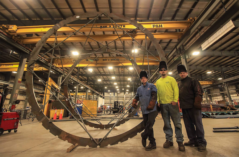
In drilled shaft construction, rebar cages are typically used to reinforce the shaft during excavation. The design of this cage is critically important to the stability of the cage and the success of the overall construction project.
As a general rule, a rebar cage for a drilled shaft consists of longitudinal bars that are distributed with equal spacing along the perimeter of a cylinder.
To reinforce these bars, steel is placed transverse to the bars, attached with ties, clamps or welds. Other components of rebar cages may include hoops for sizes, guides for centering the cages in the borehole and the premie inside of the cage, and stiffeners and pickup devices that can be used to assist in lifting the cages.
Larger cages should have temporary or permanent strengthening elements included to prevent permanent distortion from the stresses of lifting and placing.
Because rebar cages play such an important role in drilled shaft construction, it is vital that these cages be properly constructed, based on a calculation of the stresses that it will bear.
The amount of reinforcing steel in a rebar cage must satisfy structural requirements, taking into account combined stresses of axial load, lateral load and moment. Following the guidelines of this article can help to ensure that the appropriate calculations are made for the construction of rebar cages.
Properties of Steel Used for Rebar Cages
One of the most important factors for rebar cages used in drilled shaft construction is the type of steel utilized. The American Society for Testing and Materials (ASTM) specifies several steels that can be used for reinforcing drilling shafts, availing in the Annual Book of ASTM Standards.
Most of these ASTM steels are also designated by the American Association of State Highway and Transportation Officials (AASHTO) as appropriate for use in building rebar cages for drilled shaft construction.
Generally, the steel that is usually available for these cages is AASHTO M 31 (ASTM A 615) in Grade 40 or Grade 60. If welding is necessary, then weldable steel, such as ASTM A 706, can be used.
In situations where there may be an increased risk of corrosion, galvanized or epoxy-coated steel should be used for longitudinal and transverse reinforcement. This is often specified for marine environments where the chloride content of ground or surface water is high.
Because nicks and blemishes in the coating may occur during the lifting and placement of the rebar cases, accelerated corrosion may happen. This presents unique challenges in marine environments. In this case, rebar without epoxy may be used and the drilled shaft may be filled with a low-permeability concrete to increase corrosion protection.
In unusual situations, high strength reinforcement may be beneficial. This may include the use of threaded couplers for splice connections and higher-strength rebar.
Contractors should carefully calculate the structural requirements of a drilled shaft when determining the needs of a rebar cage.
Longitudinal Reinforcement of Rebar Cages
 The main role of the longitudinal reinforcing steel in rebar cages for transportation structures is to resist stresses due to bending and tension.
Even if the computed bending and tensile stresses are negligible, unanticipated lateral loads may occur. For this reason, it is good practice for contractors to provide at least some longitudinal steel reinforcement in all drilled shafts for bridge foundations.
AASHTO design specifications require that reinforcing for drilled shafts extend at least 10 feet below the plane, where the soil provides “fixity.” Under these standards, fixity is not clearly defined, so judgment as to this matter is left to the contractor and designer.
In nearly all rebar cage designs, the reinforcements must be strongest within the top diameters of the ground line, diminishing rapidly with depth.
The highest number of longitudinal bars will be required in the upper section of a drilled shaft, with some bars eliminated as the depth increases.
However, with some construction methods, it is often desirable for the rebar cage to be able to stand on the bottom of the shaft excavation during concrete placement. For this reason, at least some longitudinal bars must extend the full length of the drilled shaft.
For the concrete to function as designed, the longitudinal bars must bond to it properly. The bars must therefore be free of excessive rust, soil, oils or other contaminants. To achieve this goal, deformed bars are utilized to achieve an adequate bond.
In wet construction, as the concrete rises to displace the slurry, there is a possibility that some of the water, bentonite or polymer will be trapped around the bar deformities. If the slurry meets appropriate specifications at the time the concrete is placed, there is no evidence to suggest that there will be a significant loss of bond.
As a general rule, longitudinal bars should be spaced evenly around the rebar cage. If there are six or more bars in a symmetrical cage, then the bending resistance is almost equal in any direction.
If there are compelling reasons for non-symmetrical spacing, it is possible to vary the spacing of the longitudinal bars and to place the rebar cage in a specific direction where the main forces causing bending have a preferential direction.
Any potential material savings gained by such a procedure are typically offset by the risk of delays in inspection and construction, or the risk of the cage twisting or becoming misaligned.
There should be sufficient clear space between the longitudinal bars, as well as the transverse bars or spiral loops to allow free passage of the concrete through the cage.
This is particularly important because drilled shaft concrete is placed without vibrating the concrete.
The spacing between the bars will depend on the characteristics of the fluid concrete mixture; however, the size of the largest coarse aggregate in the mix is an important consideration.
For tremie-placed concrete, research suggests that a minimum spacing of at least eight times the largest coarse aggregate is necessary to avoid blocking. Many agencies require a minimum opening of five inches between bars, both vertically and horizontally, and at least ten times the size of the largest coarse aggregate in the mix.
If the concrete is being placed into a dry shaft, then a smaller spacing of five times the size of the largest coarse aggregate can be used.
In some instances, the steel percentage can be increased while maintaining a cage with appropriate rebar spacing by clustering or bundling two or three bars together. This may require a greater development length beyond zone maximum movement.
To provide an increased amount of steel for drilled shafts with unusually large bending movements, two concentric rebar cages may be used.
However, utilizing two cages in this manner can impede lateral concrete flow, increasing the risk of defective concrete at the perimeter of the drilled shaft and in the space between the two cages.
In these situations, contractors may consider using high-strength bars, bundled bars, or increasing the diameter of the drilled shaft.
Transverse Reinforcement of Rebar Cages
There are four primary purposes of transverse reinforcement bars in rebar cages during drilled shaft construction.
- Resisting the shearing forces that act on a drilled shaft.
- Holding the longitudinal steel in place during construction.
- Providing the drilled shaft with enough resistance against compressive or flexural stresses.
- Confining the concrete in the core of the cage to give the drilled shaft post-yield ductility. Transverse reinforcing steel is provided in one of three forms: ties, hoops or spirals.
When ties or spirals are utilized, the end of the steel must be anchored in concrete at a sufficient distance to assure that the full bar capacity is achieved at the point of connection of the two ends of the tie or the end of one spiral section and the beginning of the next.
The best practice in constructing rebar cages using ties or spirals is to anchor the transverse steel by using a sufficient amount of lapping.
The workers assembling the reinforced steel should be skilled in tying rebar so the bars will maintain their relative positions during the concrete pour.
The rebar cage itself should be assembled so that it will resist the forces caused by the concrete as it flows from the inside of the cage.
If the steel in the transverse ties is too small, deformation of the steel may occur.
The stability of rebar cages can be improved by completely tying every crossing between the longitudinal and transverse steel, rather than only tying some crossings.
Distortion of the rebar cage may also occur if the concrete flows to one side of the excavation to fill a void or an oversized excavation.
If there is any potential for these conditions, then the cage should be carefully tied and supported during concrete placement and removal of casing.
Both the cage and concrete mix should be designed to ensure that the concrete can pass through the cage. Stiffeners can also be designed to remain in the cage during concrete placement.
While rebar cages can be assembled by welding, this is not common practice in the United States. Weldable steel is not typically used in the U.S., although it can be obtained if necessary.
In seismic conditions, consideration for ductility should be taken into account.
A relatively large amount of transverse reinforcement may be required in these situations. However, this can cause difficulty with concrete flow, particularly with the use of tight spirals.
One solution is to use bundled hoops to increase the clear space between hoops.
Alternatively, a permanent steel casing to provide confinement and ductility near the top of the shaft can be used.
Finally, if very tight spiral spacing is necessary, a concrete mix with high passing ability can be utilized.
Splicing of Longitudinal Reinforcements
When the length of a rebar cage exceeds the length of available reinforcing bars, splicing will be required. As a general rule, longitudinal reinforcing bars are supplied in lengths of 60 feet or less.
Splices in these steel bars can be made by lapping the bars so that the bond in the rebar is sufficient to develop the full capacity in tension or compression in each bar at the point of the splice.
The tie wire or clamps used to connect the bars must be strong enough to allow the cage to be lifted and placed without permanent distortion of the rebar cage.
If the steel used is weldable, the bars can be spliced through welding. However, this is not commonly used in the United States.
If required, splices in longitudinal steel should be staggered so that they do not occur at the same horizontal place. No more than 50 percent of the splices should be at any one level, for both constructability as well as structural considerations.
Not only will having too many splices at the same level be less stable, but it will impede concrete flow in the drilled shaft.
Splices can also be made by the use of special connectors. These connectors are generally more expensive than lap splices, but can reduce congestion in the cage. However, these types of mechanical splices should still be staggered to maximize structural support.
In locations where large lateral loads are anticipated, many structural designers prefer to not place any splices. Similarly, many designers avoid splices in zones where the likelihood of corrosion is highest.
In situations where a rebar cage is so long that it cannot be lifted in one piece, it can be spliced in the borehole.
The lower portion is placed in the exaction and held at a working level while the upper portion is lifted and positioned so that the two can be spliced together.
Typically, wire ties or clamps are used to make the splices, with the ties or clamps staggered for stability. The entire cage is then lowered into position.
Because concrete should be placed as soon as possible after excavation, splicing inside of a borehole should be minimized or avoided whenever possible.
Connections between Drilled Shafts and Columns
The connection between the drilled shaft reinforcement and the column raises another constructability concern. There are several possible approaches to the connection design.
A major consideration that all contractors must take into account is the tolerance in design of a splice near the top of the driller shaft or the base of the column. This may present a concern for ductility in a high moment area for seismic loading.
If the design allows for a lap splice at the base of the column, a relatively simple approach is to leave the shaft reinforcement sticking above the top of the shaft by a length sufficient to form the splice. This design works best for round columns with shaft and columns of similar size.
Alternatively, the connection can be made at the top of the column for the same offset relevance of the drilled shaft.
This can be done to accommodate the location tolerance of the drilled shaft and to maintain the required concrete cover for the drilled shaft rebar cage. It allows the drilled shaft rebar cage to remain centered in the drilled shaft, while the column steel can be spliced directly to the drilled shaft rebar cage.
If a continuous longitudinal cage extending from the shaft into the column with no splices near the ground line is required, then the contractor may need to work over and around a cage that extends many feet above the shaft.
This will increase costs, due to the need for bigger cranes and more complicated concrete placement.
In certain cases, a drilled shaft that is significantly larger than the column is part of the design so that any damage from seismic over-stress conditions is confined to the base of the column above grade.
This type of connection is used in seismic areas, with a column reinforcement extended into the top of the shaft to form a “non-contact” lap splice to develop the strength of both the column and the shaft reinforcement.
If a drilled shaft reinforcement includes a connection to a cap, grade beam or abutment wall, the cage for the shaft should not include out-hook bars or other obstacles when a temporary casing is used.
If possible, these can be turned inward during installation and then rotated into position after the concrete has been placed.
Longitudinal bars can also be field bent hydraulically after the casing has been removed and both L-shaped bars or out-hooks could be included in a secondary splice cage.
Sizing Hoops
To assist in the fabrication of the rebar cage, sizing hoops are often constructed. These hoops also ensure that the finished cage diameter is correct.
The sizing hoop functions as a guide for the fabrication of the rebar cages and is often made of plain rebar or thin rolled-plate stock.
Sometimes called a “gauge hoop,” a sizing hoop can also be made with a lapped splice or with the ends of the hoop butt-welded.
The hoops are marked to facilitate the placement of longitudinal steel. These hoops give the finished cage some additional stability, but serve no structural purpose. For this reason, butt-welding on non-weldable steel is permissible.
Centering Devices
To allow enough room for fresh concrete to flow up through the annular space between the cage and the sides of the excavation and to provide adequate cover for the rebar, the completed cage must be sized properly.
According to AASHTO, minimum concrete cover should be three inches for drilled shafts with diameters of up to three feet, four inches for diameters of between three and five feet, and six inches for shaft diameters of five feet and larger.
The minimum annular space should not be less than five times the largest size of coarse aggregate in the concrete mix.
Centering devices are the best way to assure that the cage is held an appropriate distance away from the walls of the borehole or casing during the concrete placement. These devices can also be used in the interior of rebar cages to guide the termini in a wet-hole concrete placement operation.
Centering devices should be made of rollers that are aligned to allow the cage to travel along all of the drilled shaft excavation without dislodging soil or debris, or causing loose material to accumulate in the bottom of the excavation prior to concrete placement.
The rollers may be made of plastic, concrete, or mortar. They should not be made of steel which could introduce a corrosion path to the reinforcement.
Flat or crescent-shaped centralizers, known as sleds, should not be used in uncased shafts. These types of centering devices increase the risk of material being dislodged from the sides of an excavation and accumulating debris at the base of a drilled shaft excavation.
In some constructions, the base of the drilled shaft cage must be suspended off of the soil or rock in order to prevent rebar corrosion.
Centering devices can be used to reduce bearing pressure from the weight of the cage under the longitudinal bars and to prevent the rebar from penetrating into the soil where the weight of the cage is supported on the base of the excavation.
In these situations, small concrete, mortar or plastic “chairs” can be made or used for this purpose.
Strengthening the Cage
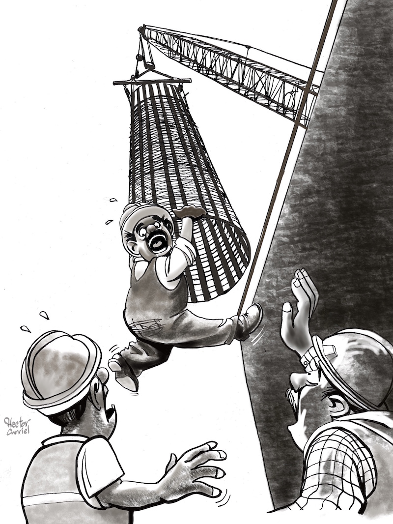
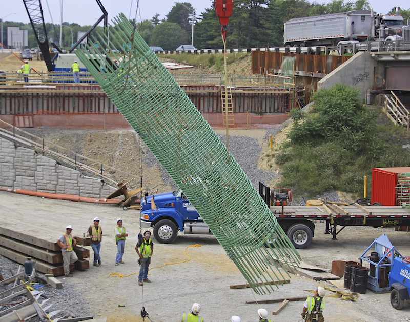
When the rebar cage is lifted from a horizontal position on the ground (its position when fabricated), rotated to vertical, and then lowered into the borehole, it may distort. This represents a critical stage in the construction of a drilled shaft. Temporary or permanent stiffening of the cage may be necessary to prevent distorting during lifting.
Temporary stiffeners that are tied to the reinforcing cage should usually be removed as the cage is held vertically and lowered into the excavation to reduce obstructions when the tremie or pump line is lowered into the excavation.
Other stiffeners may be tack-welded to the sizing hoops as they are not part of the structural reinforcement for the design.
Rebar cages may also be braced externally so that there is no need to remove bracing during placement of the cage. Contractors can do this by using a “strong-back,” or section of pipe or wide flange section tied to the cage while it is being lifted.
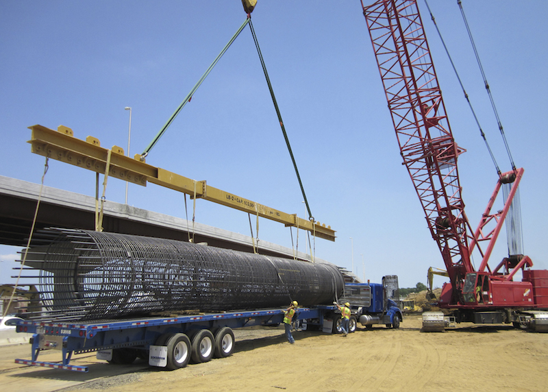
Arrangements for Lifting the Cage
To lift the rebar cage from its horizontal position on the ground to a vertical position for placement, there are two main options.
First, a contractor may use slings or temporary attachments provided by personnel on the job.
Second, hoops tied to the cage can be used to pick up the cage. Ideally, the cage should be lifted from several longitudinal rebars to avoid permanent dislocation of the rebar.
Some elastic deformation of a cage during lifting is to be expected. However, if plastic, or permanent, deformation occurs, the cage must be repaired before it is placed.
Similarly, if the ties slip or the spiral is evident after the cage is brought vertical, it must be repaired.
If the construction operation requires that the cage be self-supported at the bottom of the shelf excavation, it is vital that the cage be well-tied and free of distortion from the lifting operation.
External support from a “strong-back” can be used to help lift the cage to vertical position. Structural beams, pipes or other elements can be lifted with the cage to move it to a vertical position.
After the rebar cage has been lifted, additional roller centralizers should be attached to the rebar cage to replace any that have been damaged or are missing.
Fabrication and Storage
Constructing a rebar cage can occur in a fabrication yard. However, this brings about the expense and challenge of transporting the cage to the job site. If a site is too confined or congested, offsite fabrication may be necessary.
If construction can occur at the job site, the typical procedure is for the rebar to be transported to the job site where the cage can be assembled as close as possible to the excavation. In this manner, transportation of the cage is eliminated, and the only handling of the cage is the necessary lifting and placement.
In some situations, a contractor may even fabricate a cage directly over or in a drilled shaft excavation.
This should generally be avoided in uncased holes, since it increases the time that the excavation is open, along with the risks of hole instability and surface degradation.
In most cases, a number of cages are constructed prior to the drilling of boreholes. These cages are then stored at the job site until a cage is needed and then placed as soon as possible after an excavation.
If contractors choose to make rebar cages ahead of time, arrangements should be made to keep them free from contamination.
The design of rebar cages is critical for drilled shaft construction. Not only must they provide structural support, but they must be carefully constructed to allow for concrete passing ability and construction tolerances.
With many and often conflicting considerations involved in drilled shaft construction, including the use of rebar cages, contractors should consult with skilled engineers regarding the best solution for these issues.
View the complete article here.
What is a rebar cage?
In drilled shaft construction, rebar cages are typically used to reinforce the shaft during excavation. The design of this cage is critically important to the stability of the cage and the success of the overall construction project.
What type of steel is used in rebar?
The steel that is usually available for rebar cages is AASHTO M 31 (ASTM A 615) in Grade 40 or Grade 60. If welding is necessary, then weldable steel, such as ASTM A 706, can be used.
What are sizing hoops?
To assist in the fabrication of the rebar cage, sizing hoops are often constructed. These hoops also ensure that the finished cage diameter is correct. The sizing hoop functions as a guide for the fabrication of the rebar cages and is often made of plain rebar or thin rolled-plate stock.
What is the minimum concrete cover for drilled shafts?
According to AASHTO, minimum concrete cover should be three inches for drilled shafts with diameters of up to three feet, four inches for diameters of between three and five feet, and six inches for shaft diameters of five feet and larger.