


SPW911 Sheet Pile Design Software – Introduction and Guide

By: Carl A. Hazenberg, P.E.
Chief Engineer/Partner
Everlast Synthetic Products, LLC
This is a brief introduction to SPW911 software to give new users an overview of its main features.
Since the introduction of SPW911 software into the piling industry, it has established itself as a valuable tool for both engineers and contractors alike. To date, thousands of sheet pile structures have been constructed with the aid of this software, no doubt due to the significant amounts of time it can save engineers on evaluation and design.
Contractors with a good understanding of a project’s conditions can use it to easily provide realistic cost estimates to owners before committing to the final design stage, and it also helps with the quick and safe design of excavation and shoring systems.
SPW911 can assist in the design of bulkheads, retaining walls, cofferdams, shoring/excavation, flood walls, and dams (weirs). Sheet pile materials that have been modeled by the software include steel, vinyl, FRP composite, aluminum, timber, and reinforced concrete. The software is simple and intuitive, and requires very little learning time for the user to become both comfortable and productive.
Getting Started
 After starting the program, the user needs to agree to the disclaimer and license agreement. After doing this, a window with a typical menu bar appears containing: File, Superimpose, Miscellaneous, Database, Window, and Help. Below these dropdown menus is a Tool Bar with icons for: New, Open, Save, Print, Printer Setup, Superimpose (pressure, linear load, moment, deflection, shear, water pressure), display factor of safety, report on design safety, magnify, database, about, help, and quit. Below this are tabs for: Side Elevation, Input/Output, Graphs, and Tables.
Create a mock or test file to get started.
Database
Under the database pull down or tool bar icon there are three tabs: “Client”, “Sheet”, and “Soil”.
 A client’s information is entered under the “Client” tab.
- Likewise, the “Sheet” tab contains structural properties of several steel sheet piles. If the properties of the desired sheet pile are not in the database, it is very easy to input them. The user can enter the properties of various sheet pile materials – steel, vinyl, FRP composite, aluminum, concrete, timber, or combinations.
- The third tab is “Soils” and it offers several soil types along with typical default design parameters. Any number of soil types can be added along with their associated design strengths. Even special soil layers can be created to facilitate the analysis of flood walls and walls backfilled with concrete.
 A client’s information is entered under the “Client” tab.
Input of Project Information
Select the “Side Elevation” tab and double click somewhere on the page. A dialog box (called Define() ) will open with multiple tabs that will allow the user to input information for the project.
Under “Job” input the job/project name, location, client, phone/fax, designer, reference, and notes. Once entered, the information will display on the left side of the screen on all 5 pages.
- Select the “Setup” tab and confirm which type of units you wish to work in (Metric or Imperial/U.S.). . Enter your company’s information if you would like it to be prominently displayed at the bottom of each page. User’s company logo may be displayed as well by copying a tiff or jpeg file of the company’s logo and renaming it “MyLogo” and replacing it within the Data folder of the program.
- Choose the “Excavation” tab and enter “Depth” (this is the retained wall height or depth of excavation). “Active Water Depth” is the distance from the top of the wall to the water level behind the sheet pile wall. “Passive Water Depth” is the distance from the top of the wall to the water level in front of the sheet pile wall. This is a powerful feature, allowing the user to evaluate fluctuating water levels and their impact on the sheet pile structure with just a few clicks. Also in this section one can specify varying ground slope(s) in front and behind the sheet pile wall to evaluate changing cross section geometry(s).
- Choose the “Soils” tab to input up to 20 soil layers in the model. Pick an existing soil name from the soil database or enter each parameter individually. It is usually much easier to input soil properties from the soil database, rather than inputting each layer’s properties individually. Enter the depth to the top of the soil layer measured from the top of the wall, “d”. To add another soil layer, simply select “+” in the lower left corner of the dialog box, choose a soil type from the soil database again, enter “d” for the distance to top of that layer, and then “√”[check mark] to enter and apply the new layer. Repeat this process until all required soil layers have been inputted. A soil layer can easily be removed by picking red “X”.
 Choose the “Soils” tab to input up to 20 soil layers in the model. Pick an existing soil name from the soil database or enter each parameter individually. It is usually much easier to input soil properties from the soil database, rather than inputting each layer’s properties individually. Enter the depth to the top of the soil layer measured from the top of the wall, “d”. To add another soil layer, simply select “+” in the lower left corner of the dialog box, choose a soil type from the soil database again, enter “d” for the distance to top of that layer, and then “√”[check mark] to enter and apply the new layer. Repeat this process until all required soil layers have been inputted. A soil layer can easily be removed by picking red “X”.
Note, it is very important for the final design that good geotechnical information has been acquired for incorporation into any model or software. Bad assumptions or misunderstanding of the soils’ properties could result in a catastrophic failure. Furthermore, soft clays or silts could fail due to global (slope) stability issues which are beyond the capabilities of the SPW911 software.
Choose the pressure model, either Rankine, Coulomb, or Terzaghi. This selection impacts how the pressures are applied to the wall. The inherent differences between these methods are beyond the scope of this article to explain, but it is worth noting that Rankine is a simpler and more commonly used method than Coulomb. Terzaghi is mostly used to calculate strut/wale/bracing loads in excavations, since wale reactions using Terzaghi produce more conservative results than the other methods.
- Under the “Wall” tab. Here, the modeler can pick the sheet pile from the database or else enter sheet pile properties individually. Again, it is much easier to select a sheet pile from the database.
- Penetration of the sheet pile can be determined using Free Earth Support, Fixed Earth Support, Defined Factor of Safety, or Manually. “The Free Earth Support Method(FESM) is a classical method based on equilibrium of the driving and resisting forces/moments. When the FESM is selected, the program uses a default factor of safety of 2 for an anchored wall and a default factor of safety of 1 for a cantilever wall. The Factor of Safety referenced here is based on summing moments around the lowest frame/brace/wale for an anchored wall (point of fixity for a cantilever wall), and is the available resisting moment divided by the driving moment. This is not to be confused with a material factor of safety for overstressing the sheet pile. The Fixed Earth support method provides for slightly greater penetrations to generate greater passive resistance and reduce loading in sheet piles and anchors and provides for greater factors of safety as it relates to sheet pile penetration depth. Soil factors of safety can be selected and applied to the passive side (water side) of the sheet. Upstand is the amount of sheet pile the user can specify to extend above the backfill. Note that the upstand distance is not added to the sheet pile length calculated and displayed – the designer needs to manually add this distance for the overall sheet pile length if an “Upstand” value is inputted.
- If the sheets are not to be anchored or tied back, it is considered a cantilevered wall and no input is required for the “Support” tab. However, the default factor of safety for cantilever walls is 1. For most applications, a larger factor of safety should be selected for the cantilevered evaluation. Therefore, select “Defined FOS” and enter an appropriate value for the given project. The Factor of Safety referenced here is based on summing moments around the point of fixity, and is the available resisting moment divided by the driving moment. This is not to be confused with a material factor for overstressing the sheet pile.
- Choose the “Support” tab if the wall is to be tied-back or anchored. Enter the distance from the top of the wall to the center of a wale beam or strut. Multiple supports can be entered if desired. Selecting “Waler” or “Brace” in the selected frame will change the representation in the illustration of the Side Elevation view only. Checking the “Share load” box will split the reaction load equally between the wales selected. Strut section for “Angle” and “Anchor” selection changes the illustration display only.
 Under the “Wall” tab. Here, the modeler can pick the sheet pile from the database or else enter sheet pile properties individually. Again, it is much easier to select a sheet pile from the database.
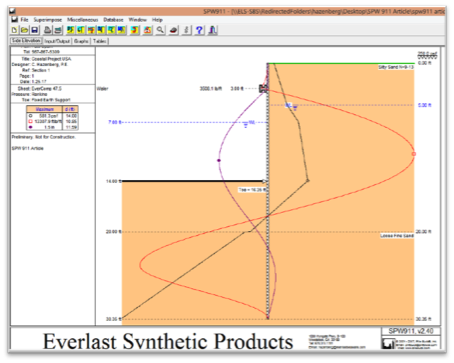 Now that all the inputs have been completed, the sheet pile wall section can be evaluated by selecting and viewing various tabs: “Side Elevation”, “Input/Output”, “Graphs” and “Tables”. These tabs are self-explanatory, but the “Side Elevation” tab is likely to be the most useful.
By selecting various icons: “P” for pressure, “L” for linear load (this is the calculated horizontal wale reaction load), “M” for moment, “D” for deflection, “F” for shear, and “W” for water pressure, you can easily superimpose the graph of the property that is being evaluated directly on the schematic drawing of the sheet pile wall. At the same time, the maximum and location of that property is noted on the left side of the page below the project and sheet information.
Selecting the icon again will turn the graph off. In this view, other important variables that impact the wall’s loading are easily examined as well – water level on the active and passive sides, wale locations and horizontal reaction load, surcharge loading, soil strata description and location, client information, project information, factor of safety, pressure method, and toe stabilization method.
The example above utilizes the properties of EverComp 47.5 composite sheet pile for a 14’ high wall, supported by a single dropped wale 2 feet from the top, two defined soil layers, 2 feet water lag, and 250 psf surcharge. The user can easily and quickly change some or all of the variables of the wall section to get a sense of the most critical design factors for the structure. Detailed graphs, tables and input/output can be reviewed and printed on separate pages if required.
SPW911 is a very effective and intuitive tool that will greatly reduce the time spent on manually making calculations. Users typically find that the product’s simplicity makes it easy to learn and use, but for safety’s sake, all users are advised to ensure that all calculations are reviewed and approved by a qualified professional before being released to clients.
You can purchase SPW911 software here.
How does SPW911 software benefit engineers and contractors in the piling industry?
SPW911 software is a valuable tool for engineers and contractors, saving significant time in evaluation and design of sheet pile structures, enabling realistic cost estimates, and ensuring quick and safe design of excavation and shoring systems.
What types of structures can SPW911 assist in designing, and what sheet pile materials does it support?
SPW911 aids in designing bulkheads, retaining walls, cofferdams, flood walls, and dams, supporting various sheet pile materials such as steel, vinyl, FRP composite, aluminum, timber, and reinforced concrete, with a simple and intuitive interface.